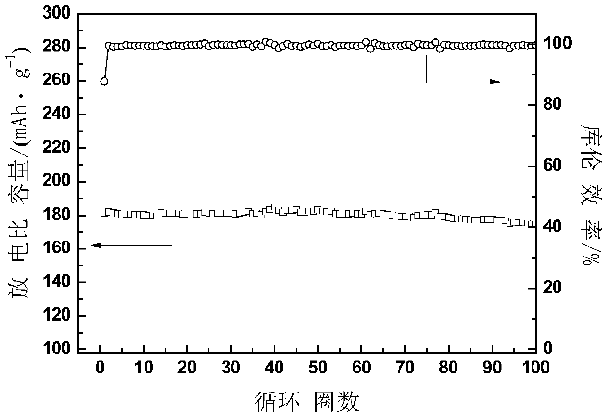
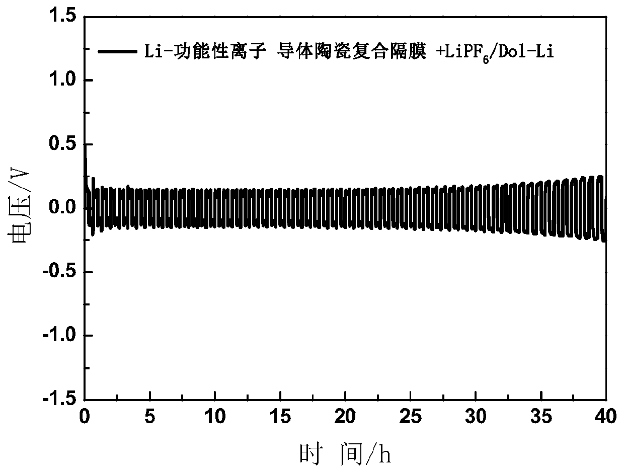
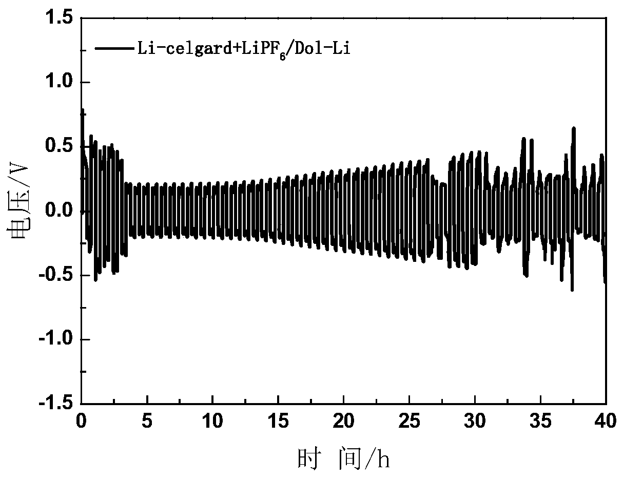
In-situ preparation method of solid-state battery
A solid-state battery, in-situ preparation technology, used in the manufacture of electrolyte batteries, secondary batteries, battery pack components, etc., can solve the problem of negative electrode lithium dendrite growth and increase in interface impedance, poor ionic conductivity of diaphragm, poor interface contact, etc. problems, to achieve the effect of high electrochemical decomposition voltage, excellent film-forming properties, and good mechanical strength
- Summary
- Abstract
- Description
- Claims
- Application Information
AI Technical Summary
Problems solved by technology
Method used
Image
Examples
Embodiment 1
[0034] Under the protective atmosphere of high-purity argon, the functional ionic conductor ceramic composite diaphragm was prepared, and the specific process was as follows:
[0035] Weigh 2g of the inorganic ceramic electrolyte, place it in a ball mill jar for dry milling, the ball milling speed is 300r / min, and the ball milling time is 30min, to obtain the oxide solid electrolyte powder. Mix the ball-milled inorganic ceramic electrolyte powder with the PVDF-HFP colloidal liquid at a mass ratio of 92:8, and stir evenly to obtain the inorganic ceramic electrolyte+PVDF-HFP mixed slurry. Under the protective atmosphere of high-purity argon, the mixed slurry is wet-coated on a 0.05mm base film with a coating thickness of 0.1mm, and then the base film is placed on a heating plate for heating and drying , the heating temperature is 60°C, and the heating time is 12h, and a functional ion conductor ceramic composite diaphragm is prepared for use.
[0036] Under the protective atmos...
Embodiment 2
[0040] Under the protective atmosphere of high-purity argon, the functional ionic conductor ceramic composite diaphragm was prepared, and the specific process was as follows:
[0041] Weigh 2g of the inorganic ceramic electrolyte, place it in a ball mill jar for dry milling, the ball milling speed is 200r / min, and the ball milling time is 60min, to obtain the oxide solid electrolyte powder. The ball-milled inorganic ceramic electrolyte powder and PVDF-HFP colloidal liquid were mixed at a mass ratio of 85:15, and stirred evenly to obtain an inorganic ceramic electrolyte+PVDF-HFP mixed slurry. Under the protective atmosphere of high-purity argon, the mixed slurry is wet-coated on a 0.05mm base film with a coating thickness of 0.1mm, and then the base film is placed on a heating plate for heating and drying , the heating temperature is 50°C, and the heating time is 24h, and a functional ionic conductor ceramic composite diaphragm is prepared for use.
[0042] Under the protectiv...
Embodiment 3
[0046] Under the protective atmosphere of high-purity argon, the functional ionic conductor ceramic composite diaphragm was prepared, and the specific process was as follows:
[0047] Weigh 2g of the inorganic ceramic electrolyte, place it in a ball mill jar for dry milling, the ball milling speed is 200r / min, and the ball milling time is 60min, to obtain the oxide solid electrolyte powder. The ball-milled inorganic ceramic electrolyte powder and PVDF-HFP colloidal liquid were mixed in a mass ratio of 90:10, and stirred evenly to obtain a mixed slurry of inorganic ceramic electrolyte + PVDF-HFP. Under the protective atmosphere of high-purity argon, the mixed slurry is wet-coated on a 0.05mm base film with a coating thickness of 0.1mm, and then the base film is placed on a heating plate for heating and drying , the heating temperature is 50°C, and the heating time is 24h, and a functional ionic conductor ceramic composite diaphragm is prepared for use.
[0048] Under the prote...
PUM
| Property | Measurement | Unit |
|---|---|---|
| Discharge specific capacity | aaaaa | aaaaa |
Abstract
Description
Claims
Application Information
 - R&D Engineer
- R&D Manager
- IP Professional
- Industry Leading Data Capabilities
- Powerful AI technology
- Patent DNA Extraction
Browse by: Latest US Patents, China's latest patents, Technical Efficacy Thesaurus, Application Domain, Technology Topic, Popular Technical Reports.
© 2024 PatSnap. All rights reserved.Legal|Privacy policy|Modern Slavery Act Transparency Statement|Sitemap|About US| Contact US: help@patsnap.com


