Vehicle-mounted self-unfolding log-periodic antenna and using method
A log-periodic antenna, self-expanding technology, applied in log-periodic antennas, antennas, folded antennas, etc., can solve the problem of inconvenient disassembly of the log-periodic antenna
- Summary
- Abstract
- Description
- Claims
- Application Information
AI Technical Summary
Problems solved by technology
Method used
Image

Examples
Embodiment 1
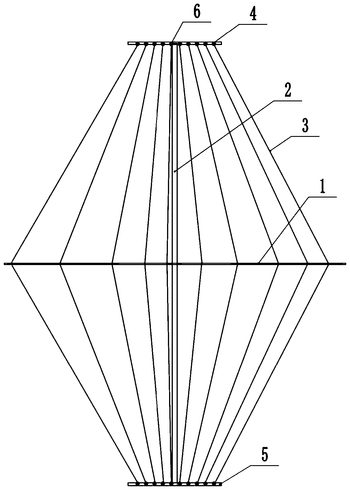
[0036] Such as Figure 1-4 As shown, a vehicle-mounted self-deploying logarithmic periodic antenna includes a main truss 1 fixed in the middle of the lifting pole 2 and an upper beam 4 and a lower beam 5 respectively fixed at the upper and lower ends of the lifting pole 2 . Wherein the lifting rod 2 is a device fixed on the top of the communication vehicle for lifting the antenna, and the lifting rod 2 is a vertical multi-stage lifting rod.
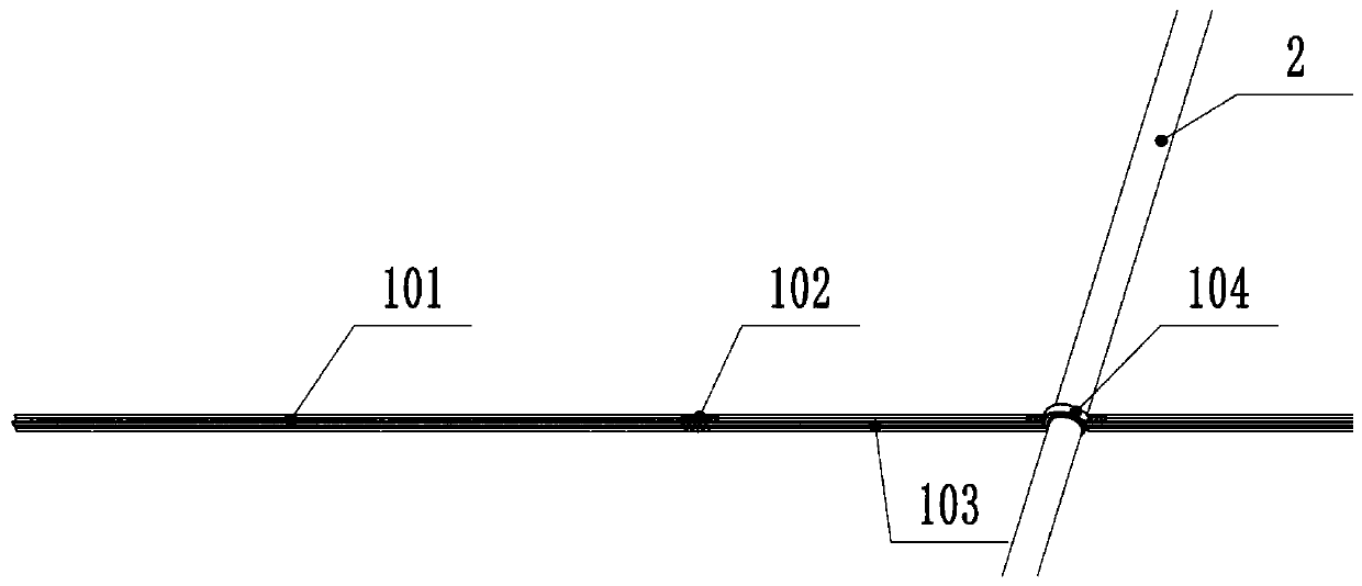
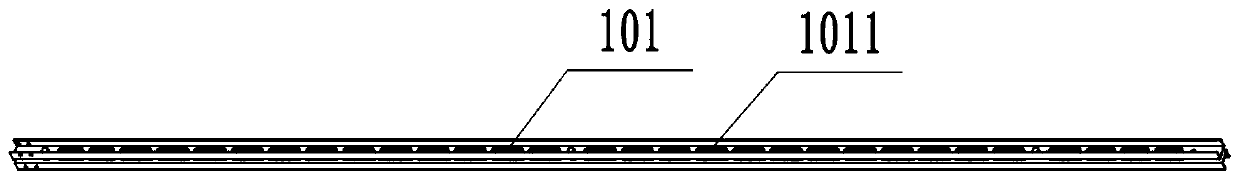
[0037] Due to the bandwidth requirements of the antenna, the total length of the main truss is 12m. For the convenience of loading, therefore, in the present embodiment, the main truss 1 includes a truss fixed rod and two truss movable rods 101 for fixing on the elevating rod 2, and the truss The fixed rod includes two truss suspension rods 103 that are arranged perpendicular to the lifting rod 2 and cantilever to both sides of the lifting rod 2 in the horizontal direction, and a lifting rod hoop that connects the two truss suspension rod...
Embodiment 2
[0041] This embodiment is basically the same as Embodiment 1, the difference is: as Figure 5-6 As shown, considering that the upper beam 4 is at the top of the elevating rod 2, the automatic wire take-up device is not easy to connect to the power supply. Therefore, in this embodiment, the automatic wire take-up device 6 includes a wire take-up wheel body and is mounted on the center of the wire take-up wheel body. The take-up wheel shaft 604 at the position, and the take-up wheel shaft 604 can rotate coaxially relative to the take-up wheel body. The take-up reel wiring portion 602 of each take-up reel limiting portion 601, and the ring-shaped area surrounded by the take-up wheel limiting portion 601 and the take-up wheel wiring portion 602 forms a take-up space for accommodating the vibrator wire 3 . In this embodiment, since the take-up wheel body is rotated and the take-up wheel shaft 604 is fixed, the take-up wheel body can obtain a longer take-up length under the same pow...
Embodiment 3
[0043] This embodiment is basically the same as embodiment one or / and two, the difference is: as figure 1 with 7 As shown, the vibrator wire 3 includes an insulating pull rope 301 and a conductor 302 wrapped outside the insulating pull rope 301. The conductor 302 is a conductive copper mesh and an insulating sheath 303 coated on the outside of the conductor 302. The vibrator wire 3 One end of the insulating pull rope 301 is bound on the main truss 1, and the other end is fixed on the automatic wire take-up device 6. In addition, one end of the conductor 302 of the vibrator wire 3 is conductively connected with the corresponding feeding point on the main truss 1. Since the antenna is in Considering the electrical performance such as bandwidth, the end of the vibrator wire 3 away from the main truss 1 is provided with an extended vibrator 7, and the extended vibrator 7 is arranged parallel to the direction of the main truss 1, and the wiring part 602 of the take-up wheel is a ho...
PUM
 Abstract
Description
Claims
Application Information
 - R&D
- Intellectual Property
- Life Sciences
- Materials
- Tech Scout
- Unparalleled Data Quality
- Higher Quality Content
- 60% Fewer Hallucinations
Browse by: Latest US Patents, China's latest patents, Technical Efficacy Thesaurus, Application Domain, Technology Topic, Popular Technical Reports.
© 2025 PatSnap. All rights reserved.Legal|Privacy policy|Modern Slavery Act Transparency Statement|Sitemap|About US| Contact US: help@patsnap.com