A Thin Film Bulk Acoustic Resonator with High Quality Factor

A thin-film bulk acoustic wave, high quality factor technology, applied in impedance networks, electrical components, etc., can solve the problems of resonator quality factor damage, acoustic wave energy leakage, etc., and achieve high Q value, low loss, and good piezoelectricity.

Active Publication Date: 2021-09-07
NO 55 INST CHINA ELECTRONIC SCI & TECHNOLOGYGROUP CO LTD
View PDF8 Cites 0 Cited by
  • Summary
  • Abstract
  • Description
  • Claims
  • Application Information

AI Technical Summary

Problems solved by technology

However, part of the acoustic energy in this technical solution will still leak to the external area through the air bridge structure, which will still greatly damage the quality factor of the resonator

Method used


Image

  • A Thin Film Bulk Acoustic Resonator with High Quality Factor
  • A Thin Film Bulk Acoustic Resonator with High Quality Factor
  • A Thin Film Bulk Acoustic Resonator with High Quality Factor

Examples


Embodiment 1

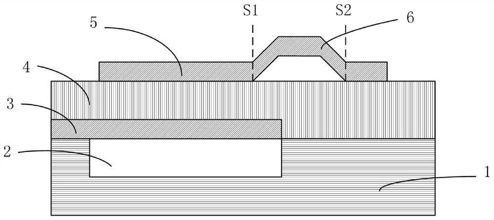
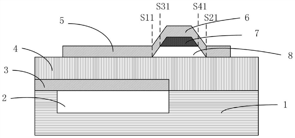
[0024] Example 1. combine Figure 2A and Figure 2B , the basic structure of a thin film bulk acoustic resonator with a high quality factor proposed by the present invention includes a substrate 1 with a groove 2 on the upper surface, a bottom electrode layer 3 above the substrate 1, a piezoelectric layer 4, a strip There is a top electrode layer 5 with an air bridge structure 6, wherein the air bridge structure 6 is provided with an acoustic rebound structure 7 that can rebound the transverse sound wave and improve the quality factor of the film bulk acoustic resonator; The boundary in one direction of the structure 6 is located inside the groove 2, and the boundary in the other direction extends beyond the boundary of the groove 2; the acoustic rebound structure 7 is in close contact with the air bridge structure 6, forming an acoustic wave in the horizontal propagation direction. Impedance mismatch interface; the material of the acoustic rebound structure 7 is a thin film...

Embodiment 2

[0039] Example 2. Taking a specific 2.6GHz thin film bulk acoustic resonator as an example, using the above-mentioned embodiment 1 of the structure, the actual effect of the present invention on improving the Q value of the thin film bulk acoustic resonator is verified and analyzed through the simulation design results.

[0040] image 3 It is a schematic diagram of the performance test parameters of the film bulk acoustic resonator without the air bridge structure. Figure 4 It is a schematic diagram of performance test parameters of a film bulk acoustic resonator with an air bridge structure. Figure 5 It is a schematic diagram of the performance test parameters of Example 1 of a thin-film bulk acoustic resonator with high quality factor proposed by the present invention. exist image 3 In the simulation design results of the thin film bulk acoustic resonator without the air bridge structure shown, the Q value of the thin film bulk acoustic resonator is 1065.762; Figure...


PUM


Abstract

The present invention relates to a thin film bulk acoustic resonator with high quality factor, comprising a substrate 1 with a groove 2 on the upper surface, a bottom electrode layer 3 above the substrate 1, a piezoelectric layer 4, and an air bridge structure 6 The top electrode layer 5 is characterized in that the air bridge structure 6 is provided with an acoustic rebound structure 7 that can rebound the transverse sound wave and improve the quality factor of the film bulk acoustic resonator; the acoustic rebound structure The material of 7 is a film medium; the acoustic rebound structure 7 is horizontally arranged in the area above the bridge cavity in the air bridge structure 6, and the bottom end surface of the rebound structure 7 is suspended from the area below the bridge cavity of the air bridge structure 6 An air gap 8 is left between the structures, and the top surface of the acoustic rebound structure 7 is in close contact with the upper surface of the bridge cavity of the air bridge structure 6, and the left side and the right side of the acoustic rebound structure 7 are respectively connected to The adjacent inner surfaces of the bridge cavity support structure of the air bridge structure 6 are in close contact. The invention can significantly improve the quality factor of the film bulk acoustic wave resonator.

Description

technical field [0001] The invention relates to a thin film bulk acoustic wave device, in particular to a thin film bulk acoustic wave resonator with high quality factor. Background technique [0002] With the development of wireless communication technology and smart phones, the RF front-end has higher and higher requirements on the performance indicators and integration of components. RF front-end filters, duplexers, and multiplexers based on thin film bulk acoustic wave devices have been widely used in smartphones, communication terminals, and In the communication base station, it will be applied in the communication equipment of the Internet of Vehicles, industrial control and other Internet of Things terminals in the future. In addition, oscillators based on thin film bulk acoustic wave devices are of great application value in high-speed serial data devices such as SATA hard drives, USB3.0 standard PC peripherals, C-type interfaces, and optical transceivers. [0003]...

Claims


Application Information

Patent Timeline
Patent Type & Authority Patents(China)
IPC IPC(8): H03H9/02H03H9/17
CPCH03H9/02086H03H9/171
Inventor 赵洪元朱健
Owner NO 55 INST CHINA ELECTRONIC SCI & TECHNOLOGYGROUP CO LTD
Why Eureka
Try Eureka