
Non-stop feeding assembly for workpiece cleaning equipment

A technology for cleaning equipment and workpieces, which is applied in the direction of conveyor objects, transportation and packaging, etc. It can solve the problems of affecting cleaning efficiency and shortening the service life of turntable motors, so as to improve cleaning efficiency, reduce the possibility of feeding failure, and ensure accurate sexual effect

Active Publication Date: 2020-05-01
WENZHOU POLYTECHNIC
View PDF5 Cites 2 Cited by
  • Summary
  • Abstract
  • Description
  • Claims
  • Application Information

AI Technical Summary

Problems solved by technology

[0004] The above-mentioned workpiece cleaning equipment has certain disadvantages. The feeding tube of the feeding assembly and the transmission groove of the turntable need to be accurately centered to ensure that the workpiece will not be stuck on the edge of the transmission groove due to burrs or irregular shapes, resulting in failure to discharge, and In order to avoid the occurrence of eccentricity, the turntable needs to stop rotating every time. After the loading is completed, it rotates to the next transmission tank and stops rotating again after aligning with the loading assembly. Such repeated start and stop not only greatly affects the cleaning efficiency, At the same time, it also shortens the service life of the turntable motor, and the cleaning process often does not require the turntable to stop rotating for cleaning. For example, the entire equipment turntable can continue to rotate and clean without stopping the rotation of the turntable during the feeding process.

Method used


Image

  • Non-stop feeding assembly for workpiece cleaning equipment
  • Non-stop feeding assembly for workpiece cleaning equipment
  • Non-stop feeding assembly for workpiece cleaning equipment

Examples


Embodiment Construction

[0031] The technical solutions of the present invention will be clearly and completely described below in conjunction with the accompanying drawings. Apparently, the described embodiments are some of the embodiments of the present invention, but not all of them. Based on the embodiments of the present invention, all other embodiments obtained by persons of ordinary skill in the art without making creative efforts belong to the protection scope of the present invention.

[0032] In the description of the present invention, it should be noted that the terms "center", "upper", "lower", "left", "right", "vertical", "horizontal", "inner", "outer" etc. The indicated orientation or positional relationship is based on the orientation or positional relationship shown in the drawings, and is only for the convenience of describing the present invention and simplifying the description, rather than indicating or implying that the referred device or element must have a specific orientation, ...


PUM


Abstract

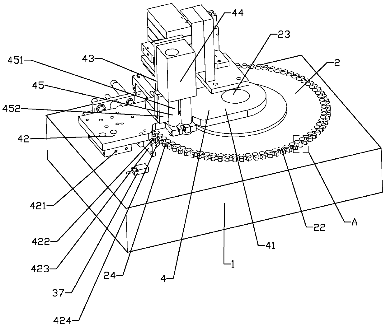
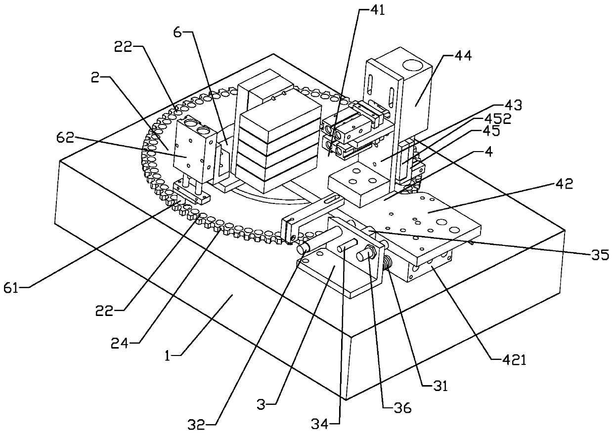
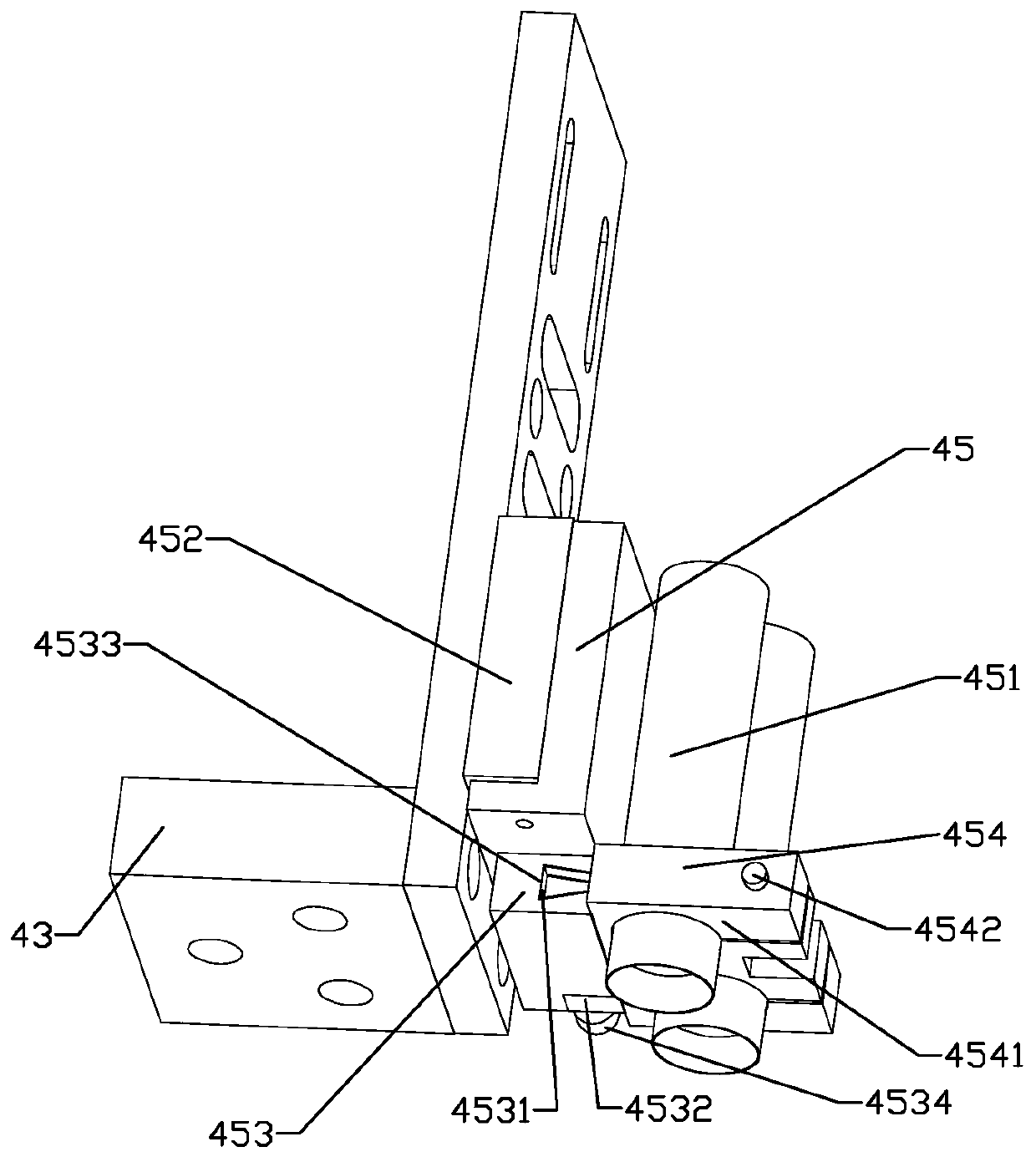
The invention relates to a non-stop feeding assembly for workpiece cleaning equipment. The non-stop feeding assembly comprises a rack, a rotating disc horizontally rotating relative to the rack, and arotating disc motor for driving the rotating disc to rotate; the rotating disc is provided with a transmission groove; a return seat and a feeding arm are further included; and a synchronous swing mechanism is arranged between a swing end and the side face of the rotating disc, a reset piece and a limiting piece are arranged between the return seat and the feeding arm, and a feeding seat is provided with a material controlling mechanism and a guiding mechanism. In the feeding process of the feeding arm, the swing end synchronously swings along with the rotating disc through the synchronous swing mechanism, the material controlling mechanism and the guiding mechanism are stably kept to be aligned with the transmission groove in the synchronous swing process of the swing end, and thus non-stop stable feeding is achieved; and after feeding is completed, the synchronous swing mechanism relieves synchronous swing of the swing end and the rotating disc, and the reset piece makes the swing end reset towards the return seat until reaching an initial position, and waits for next feeding. By adopting the non-stop feeding assembly for the workpiece cleaning equipment, the cleaning efficiencyis improved.

Description

technical field [0001] The invention relates to the field of workpiece cleaning equipment, in particular to a non-stop feeding assembly of workpiece cleaning equipment. Background technique [0002] The workpiece cleaning equipment is a device that automatically washes the workpiece through a specific cleaning fluid after the shape of the workpiece is processed. Due to its high cleaning efficiency, it is widely used in processing factories. [0003] The traditional workpiece cleaning equipment includes a frame and a turntable set on the frame, a turntable motor, a feeding assembly, a cleaning assembly and a discharging assembly. The turntable rotates horizontally on the frame and is driven by the turntable motor. The edge of the turntable There is a transfer trough for transferring workpieces to be processed. The feeding assembly, cleaning assembly and discharging assembly are arranged on the outer periphery of the turntable along the transfer direction of the turntable. The...

Claims


Application Information

Patent Timeline
Patent Type & Authority Applications(China)
IPC IPC(8): B65G47/04B65G47/80B65G47/90
CPCB65G47/04B65G47/80B65G47/90
Inventor 黄其祥
Owner WENZHOU POLYTECHNIC
Learn More