
Yarn State Detection Method Based on Contour Line Analysis

A state detection and contour line technology, applied in textiles, papermaking, knitting, etc., can solve the problems of easy interference, narrow detection area, large gain of amplifier circuit, etc., and achieve the effect of reliable operation and simple principle.

Active Publication Date: 2021-08-13
安徽尧舜智能袜业有限公司
View PDF8 Cites 0 Cited by
  • Summary
  • Abstract
  • Description
  • Claims
  • Application Information

AI Technical Summary

Problems solved by technology

This method has the advantages of simple principle and low cost, but the gain of the amplifier circuit is very large, it is easy to be interfered, and the detection area is very narrow, which requires high installation

Method used

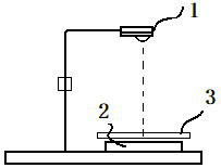
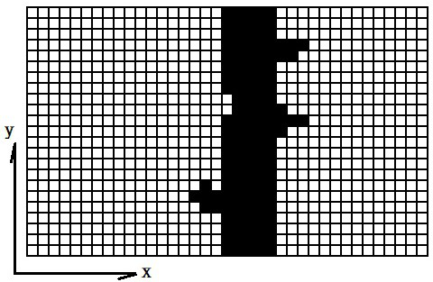
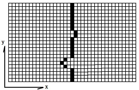

Image

  • Yarn State Detection Method Based on Contour Line Analysis
  • Yarn State Detection Method Based on Contour Line Analysis
  • Yarn State Detection Method Based on Contour Line Analysis

Examples


Embodiment Construction

[0018] Now in conjunction with accompanying drawing, the present invention will be further described:

[0019] refer to figure 1 -3. A yarn state detection method based on contour line analysis, a U-shaped casing, and an electronic control device arranged inside the casing, the electronic control device includes a power supply circuit for supplying power, and a circuit for calculation and processing A processor, an infrared emitting unit 1 and an image sensor 2 connected to the processor, and an infrared filter 3 is arranged on the image sensor 2 .

[0020] The power supply circuit converts the input power level and stabilizes the voltage to provide power for other circuits.

[0021] The image sensor 2 is configured as a CCD linear image sensor or a CMOS linear image sensor sensitive to infrared rays, and the processor can read image data as required.

[0022] The infrared filter 3 can filter out light other than infrared light, which can greatly improve environmental adapta...


PUM


Abstract

The invention discloses a yarn state detection method based on contour line analysis. A U-shaped casing is arranged, and an electronic control device arranged inside the casing includes a power supply circuit for supplying power and a processor for computing and processing, and is connected to the processor. An infrared emitting unit and an image sensor, an infrared filter is arranged on the image sensor, the infrared emitting unit is arranged directly above the image sensor, and the processor is used to realize the yarn state detection method, the steps are: (1), the processor collects the output of the image sensor image data of f t (x, y); (2), using the binarization algorithm, the image data f t (x,y) is binarized to get y t (x,y); (3), extract binary function y t Contour line y` of (x,y) t (x,y); (4), extract the contour line y` t Numerical descriptor R of (x,y) t ; (5), compared numerical descriptor R t with R t‑1 : when|R t -R t‑1 |When it is greater than or equal to the preset threshold K, it is determined that the yarn is in a moving state; otherwise, it is determined that the yarn is in a static state.

Description

technical field [0001] The invention relates to a yarn state detection method based on contour line analysis, which belongs to the technical field of textile electronics. Background technique [0002] The fully automated seamless underwear machine, as well as the automated sock machine, can completely weave one piece and one sock without human intervention. Unmanned and high efficiency can lead to increased production and reduced costs, but if a group of yarns are broken or missing, if not found in time, the entire garment will be scrapped. Therefore, yarn state detection has become an indispensable equipment for seamless underwear machines and socks machines. The currently used yarn state sensor uses a differential infrared photosensitive diode for detection. This method has the advantages of simple principle and low cost, but the gain of the amplifying circuit is very large, it is easy to be interfered, and the detection area is very narrow, which requires high installat...

Claims


Application Information

Patent Timeline
Patent Type & Authority Patents(China)
IPC IPC(8): D04B35/10D04B35/14
CPCD04B35/10D04B35/14
Inventor 刘瑜
Owner 安徽尧舜智能袜业有限公司
Learn More