Intelligent broken yarn monitoring system based on big data AI for embroidery device

An intelligent monitoring system and big data technology, applied in the direction of embroidery machine, embroidery machine mechanism, textile and papermaking, etc., can solve the problems of affecting processing efficiency, easy to break yarn, time-consuming and labor-intensive, etc., to ensure continuity, improve The effect of textile processing efficiency

Active Publication Date: 2020-05-01
艾百合纺织科技(安徽)有限公司
6 Cites 0 Cited by

AI-Extracted Technical Summary

Problems solved by technology

[0002] In the textile field, the wire feeding mechanism is an essential and important part of automatic production systems such as embroidery and knitting. However, due to improper operation or performance problems of the wire itself, the wire feeding mechanism is o...

Method used

[0030] Preferably, the wire between the first wire feed roller 60 and the second wire feed roller 80 is in a slack state, and between the first wire feed roller 60 and the second wire feed roller 80, a A remaining amount detection mechanism 70 for the remaining amount of the slack thread, the detection signal output end of the remaining amount detecting mechanism 70 is electrically connected to the data processi...

Abstract

The invention belongs to the technical fields of spinning and intelligent manufacturing, and particularly relates to an intelligent broken yarn monitoring system based on big data AI for an embroiderydevice. The system comprises a wire coil, a wire feeding device, a first detection mechanism, a second detection mechanism, a wire connecting mechanism, a data processing module, a data storage module, a central processing unit and a driving module. According to the intelligent broken yarn monitoring system, before silk yarn is conveyed to downstream equipment, the tensile strength of the silk yarn is detected firstly, compared with tensile experiment data of the silk yarn, it is guaranteed that the silk yarn meets the strength requirement, and when a weak point appears on the silk yarn, thesilk yarn can be actively broken from the weak point, the controllability of a disconnection position is guaranteed, the gravity center of the silk yarn is connected by quickly avoiding the disconnection position, uncontrollable breakage of the silk yarn in the spinning process is avoided, the continuity of equipment production is guaranteed, and the spinning processing efficiency is improved.

Application Domain

Embroidering machines apparatus

Technology Topic

Process engineeringYarn +8

Image

  • Intelligent broken yarn monitoring system based on big data AI for embroidery device
  • Intelligent broken yarn monitoring system based on big data AI for embroidery device
  • Intelligent broken yarn monitoring system based on big data AI for embroidery device

Examples

  • Experimental program(2)

Example Embodiment

[0027] Example 1
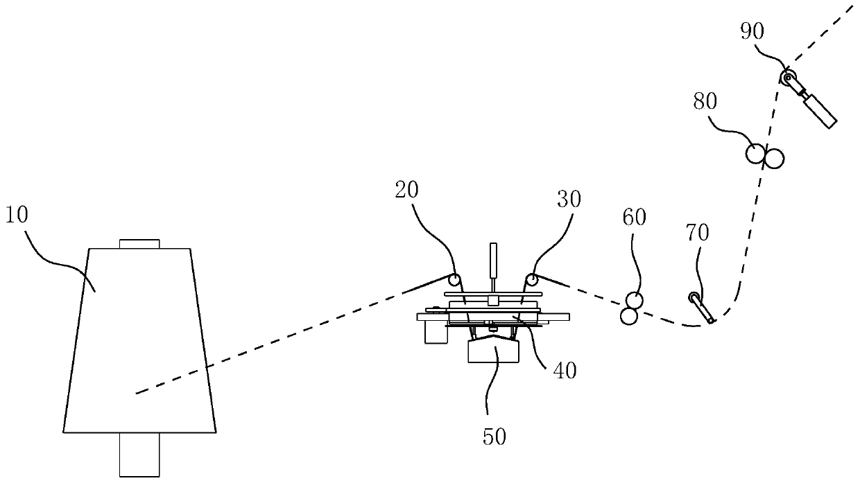
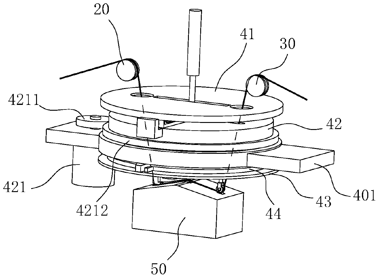
[0028] Such as figure 1 As shown, an intelligent monitoring system for yarn breakage of an embroidery device based on big data AI includes a thread reel 10 for outputting silk thread, and a wire feeding device for conveying the silk thread on the thread reel 10 to an embroidery mechanism. The first detection mechanism 50 for the tensile strength of the thread inside the silk device, the second detection mechanism 90 for detecting the thread tension between the wire feeding mechanism and the embroidery mechanism, and the second detection mechanism 90 when the thread on the first detection mechanism 50 is disconnected. The reconnected wiring mechanism 40, and the data processing module, the data storage module, the central processing unit and the drive module; the data processing module is used to receive the detection signals of the first detection mechanism 50 and the second detection mechanism 90, and the data The storage module is used to store the experimental detection data of the ultimate tensile strength of the thread and the real-time detection data of the first detection mechanism 50 and the second detection mechanism 90. The central processing unit is used to compare the real-time detection data with the stored data and compare A control signal is sent to the driving module for the result, and the driving module sends a driving signal to the wire feeder, the first detection mechanism 50 and the wiring mechanism 40 according to the received control signal. The yarn breakage intelligent monitoring system of the present invention first detects the tensile strength of the silk thread before transporting it to the downstream equipment, and compares it with the tensile test data of the silk thread to ensure that the silk thread meets the strength requirements, and when the silk thread appears weak The invention can actively disconnect the thread from the weak point, ensure that the disconnection position is controllable, and quickly avoid the disconnection to connect the center of gravity of the thread, avoid uncontrollable breakage of the thread during the weaving process, and ensure the equipment The continuity of production improves the efficiency of textile processing.
[0029] Preferably, the wire feeding mechanism includes a first guide wheel 20, a second guide wheel 30, a first wire feeding roller 60 and a second wire feeding roller 80, wherein the first wire feeding roller 60 and the second wire feeding roller 80 are The power roller and its drive signal receiving end is electrically connected to the drive signal output end of the drive module. The wiring mechanism 40 and the first detection mechanism 50 are located between the first guide wheel 20 and the second guide wheel 30. The second detection The mechanism 90 is located between the second thread feeding roller 80 and the embroidery mechanism. The thread output from the thread reel 10 sequentially bypasses the first guide wheel 20, the wiring mechanism 40, the first detection mechanism 50, the wiring mechanism 40, and the second guide wheel. 30. The first wire feeding roller 60, the second feeding roller and the second detecting mechanism 90 are arranged.
[0030] Preferably, the wire between the first wire feeding roller 60 and the second wire feeding roller 80 is in a relaxed state, and there is a wire between the first wire feeding roller 60 and the second wire feeding roller 80 for detecting the slack length of the wire. A remaining amount detecting mechanism 70 of the remaining amount, the detection signal output end of the remaining amount detecting mechanism 70 is electrically connected to the data processing module. In the present invention, the first wire feeding roller 60 and the second wire feeding roller 80 are provided with a wire allowance. When the wire in the wire feeding mechanism is broken, the allowance can ensure that the wire continues to be continuously conveyed downstream, and the broken wire passes through The wiring device is quickly connected to achieve continuous production of equipment.
[0031] Specific, such as Picture 10 As shown, the first detection mechanism 50 includes a wire pressing unit and a wire drawing unit, and a detection unit disposed between the wire pressing unit and the wire drawing unit. The wire pressing unit includes a pressing head 53 and a pressing seat 54. 53 and the pressing seat 54 abut each other, the pressing seat 54 is mounted on a lifting seat 55, the lifting seat 55 is connected with a linear drive element 57 arranged vertically, the linear drive element 57 is a linear motor, the drive of the linear drive element 57 The signal receiving end is electrically connected to the driving signal output end of the driving module. A fourth elastic unit 56 is provided between the pressing seat 54 and the lifting seat 55, and the fourth elastic unit 56 is a compression spring; the pulling unit includes a wire pressing wheel 51 and a driving wheel 52 that abuts against the wheel surface of the crimping wheel 51, the driving wheel 52 is drivingly connected to the main shaft of the driving motor 521, and the driving signal receiving end of the driving motor 521 is electrically connected to the driving signal output end of the driving module; The detection unit includes a floating roller 58 movably arranged in the vertical direction. The floating roller 58 is rotatably arranged on a floating seat 581. The bottom of the floating seat 581 is provided with a first pressure sensor 59. The detection signal of the first pressure sensor 59 is output. The end is electrically connected to the detection signal receiving end of the data processing module. The thread passes between the pressing head 53 and the contact surface of the pressing seat 54 and bypasses the floating roller 58, and then from the pressing wheel 51 and the driving wheel 52 passes between the wheels. By controlling the height of the lifting seat 55, the compression amount of the fourth elastic unit 56 can be adjusted, thereby controlling the clamping force of the pressing head 53 and the pressing seat 54, and finally realizing the control of the wire tension.
[0032] Preferably, the margin detection mechanism 70 is a swing switch, and the swing lever of the swing switch overlaps the thread between the first wire feeding roller 60 and the second wire feeding roller 80. The second detection mechanism 90 includes a supporting wheel, which is rotatably arranged on a movable base, and the movable base is movably connected with the frame, and a second pressure sensor is provided between the movable base and the frame. The detection signal of the second pressure sensor is The output terminal is electrically connected with the detection signal receiving terminal of the data processing module.
[0033] Specific, such as Figure 2-9 As shown, the crimping wheel 51 and the pressure head 53 are movably arranged in the vertical direction, and both are driven by a vertical cylinder, and the control valve of the vertical cylinder is electrically connected to the drive module; the wiring mechanism 40 includes a crimping wheel A wiring hole 423 is provided on the downward path of 51 and the indenter 53, the wall of the wiring hole 423 is provided with a gas injection hole 424, the gas injection hole 424 is in communication with the high-pressure gas source, and the gas injection hole 424 is provided with the high-pressure gas source. Solenoid valve, the drive signal receiving end of the solenoid valve is electrically connected to the drive signal output end of the drive module; it also includes a wire crimping wheel 51 for bundling the two wires between the first guide wheel 20 and the second guide wheel 30 The binding device in the wiring hole 423, and a shearing mechanism 46 for cutting the lower end of the wiring hole 423; the binding device includes an upper fixing layer 41, a revolving layer 42 and a lower fixing layer arranged sequentially from top to bottom Layer 43, the upper fixing layer 41 is provided with a threading hole 411 and a threading hole 412 for the thread to pass through. The thread thread passes through the threaded hole 411 from top to bottom and passes through from bottom to top. Hole 412; the revolving layer 42 is provided with a flat hole 422 that penetrates the upper and lower ends of the revolving layer 42; the lower fixing layer 43 is provided with a strip-shaped escape hole 431, the length of the strip-shaped escape hole 431 and the penetration The direction of the central line between the hole 411 and the through hole 412 is parallel; the crimping wheel 51 reciprocates in the channel formed by the flat hole 422 and the escape hole; the rotating layer 42 is rotatably arranged on the frame 401 and rotates The layer 42 is rotated and arranged between the following two stations: station one, the length direction of the flat hole 422 is parallel to the direction of the line connecting the centers of the penetration hole 411 and the penetration hole 412, and the flat hole 422 is in the first parallel state at this time. And station two, after the revolving layer 42 is rotated by 180°, the length direction of the flat hole 422 is again parallel to the direction of the line connecting the centers of the penetration hole 411 and the penetration hole 412, and the flat hole 422 is in the second parallel state; The frame 401 is provided with a wire drive motor 421 for driving the rotation layer 42 to rotate. The main shaft of the wire drive motor 421 is provided with a driving gear 4211. The outer circumference of the rotation layer 42 is provided with an outer ring gear 4212, a driving gear 4211 and external gears. The ring 4212 is engaged, and the drive signal receiving end of the wiring drive motor 421 is electrically connected to the drive signal output end of the drive module; the wiring hole 423 is located in the center of the flat hole 422 and is arranged through the flat hole 422. A movable door 441 for connecting and disconnecting the connection hole 423 and the flat hole 422 is provided on the side wall. The movable door 441 is assembled to open when the revolving layer 42 is in the first parallel state. At this time, the connection hole 423 It penetrates the flat hole 422, and the movable door 441 is closed when the revolving layer 42 is in the second parallel state. At this time, the movable door 441 isolates the wiring hole 423 from the flat hole 422 so that the wiring hole 423 forms a circumferentially closed channel; The door 441 includes two arc-shaped door panels symmetrically arranged on the inner wall of the wiring hole 423. The lower end of the arc-shaped door panel protrudes from the bottom surface of the revolving layer 42, and the protruding part passes The connecting rod is fixedly connected to the follower layer 44 provided under the revolving layer 42. The follower layer 44 is rotationally connected to the revolving layer 42 through an annular damping track so that the follower layer 44 can follow the revolving layer 42 without being blocked by the outside. Rotating, a limit mechanism for limiting the rotation angle of the following layer 44 is provided between the following layer 44 and the frame 401, and the limit mechanism is assembled to rotate the rotating layer 42 from the first parallel state to the second parallel state. When the follower layer 44 rotates 90° from the initial position, it is blocked by the limit mechanism and stops rotating. When the rotating layer 42 rotates from the second parallel state to the first parallel state, the follower layer 44 reverses 90° Then it is blocked by the limit mechanism and stays at the initial station; when the follower layer 44 is in the initial station and the revolving layer 42 is in the first parallel state, the movable door 441 is in the open state, and when the follower layer 44 is rotated 90° and revolves The movable door 441 is closed when the layer 42 is in the second parallel state; the limiting mechanism includes two limiting blocks 443 arranged on the frame 401 along the circumferential direction of the follower layer 44 at an interval of 90°, and the edge of the follower layer 44 is arranged The stop block 442 that blocks the two stop blocks 443.
[0034] The specific working principle of the wiring mechanism 40 is as follows: when the thread on the first detection mechanism 50 is disconnected, the crimping wheel 51 and the indenter 53 move up to the top of the revolving layer 42, and then the revolving layer 42 rotates 180°. The two strands of wire under the hole 411 and the hole 412 are guided by the flat hole 422 to close together and fall into the wiring hole 423. At the same time, because the movable door 441 only rotates 90° under the action of the limit mechanism, the movable door 441 can It is enclosed with the wiring hole 423 to form a closed channel. It should be noted that the movable door 441 can be completely closed after the revolving layer 42 is rotated at least 120°, and the silk thread is enough to fall into the wiring hole 423; when the revolving layer 42 is rotated in place, shear Cut the wire below the wiring hole 423 to remove the wires that do not meet the strength required; after the wiring hole 423 is closed, the air nozzle starts to spray high-pressure air, and at this time the two thread ends are untwisted under the action of the high-pressure air and tightly wound each other Together; then the revolving layer 42 is turned over by 180°, at this time, the indenter 53 and the crimping wheel 51 are again controlled to go down, and the connected thread is re-pressed on the first detection mechanism 50, and the thread connection is completed.
[0035] Further, the upper end of the revolving layer 42 is also provided with a clamping mechanism, and the clamping mechanism is assembled such that the clamping mechanisms are mutually opened when the revolving layer 42 is in the first parallel state, and when the revolving layer 42 is in the second parallel state. The clamping mechanism clamps the two strands of wire at the upper end of the wiring hole 423 and blocks the upper end of the wiring hole 423; the clamping mechanism includes two clamping plates 45 arranged symmetrically about the center line of the wiring hole 423, and the two clamping plates 45 rotate along the line The layer 42 is movably arranged radially, and the opposite ends of the two clamping plates 45 are provided with V-shaped clamping grooves. The two V-shaped clamping grooves are arranged staggered up and down. When the two clamping plates 45 are closed, the two V-shaped clamping grooves are closed so that only two wires can pass through. The first elastic unit 453 is provided between the splint 45 and the revolving layer 42. The first elastic unit 453 is a compression spring. The first elastic unit 453 is assembled so that its elastic force can drive the splint 45 to The center of the revolving layer 42 slides; between the splint 45 and the upper fixed layer 41 is provided a driving assembly for driving the two splints 45 to separate from each other. The driving assembly includes a first arched protrusion 457 fixedly connected to the splint 45, and The first arcuate driving block 456 fixed to the fixed layer 41 is located on the revolving path of the first arcuate protrusion 457, and when the revolving layer 42 is in the first parallel state, the first arch The convex block 457 is in contact with the first arcuate driving block 456, and the two splints 45 are separated from each other under the pushing action of the first arcuate driving block 456; the splint 45 and the revolving layer 42 are also provided Locking mechanism, the upper fixed layer 41 is provided with an unlocking mechanism, the locking mechanism is assembled to be able to keep the splint 45 in the separated state in the separated state; the unlocking mechanism is assembled to be when the rotating layer 42 is located In the two parallel states, the unlocking mechanism can unlock the locking mechanism so that the two clamping plates 45 are closed with each other under the action of the first elastic unit 453. The clamping mechanism can clamp the upper part of the terminal to be connected, and at the same time, close the upper end of the terminal hole 423 to ensure that the high-pressure airflow flows downward so that the lower terminal is fully untwisted and wound.
[0036] Preferably, the locking mechanism includes a locking pin 452 arranged vertically and telescopically at the upper end of the revolving layer 42, and a locking hole 451 opened on the clamping plate 45 that cooperates with the locking pin 452. The locking The pin 452 has a stepped shaft structure and the diameter of the upper end of the locking pin 452 is smaller than the diameter of the lower end. The locking hole 451 includes an arc part and a straight part that penetrate each other, and the diameter of the arc part is the same as the diameter of the lower end of the locking pin 452 , The width of the straight portion is consistent with the diameter of the upper end of the locking pin 452, the straight portion is arranged along the radial direction of the revolving layer 42, and the arc portion is located at the end of the straight portion away from the center of the revolving layer 42; the locking pin 452 and the revolving layer 42 A second elastic unit 455 is provided in between. The second elastic unit 455 is a compression spring, and the second elastic unit 455 is assembled so that its elastic force can drive the locking pin 452 to pop up to a high position; the unlocking mechanism includes an upper fixing layer The convex part 454 provided at the lower end of 41 is located on the rotation path of the locking pin 452. When the rotating layer 42 rotates to the second parallel state, the convex part 454 abuts against the upper end of the locking pin 452 and the locking pin 452 Go down to the low position under the pushing action of the convex part 454; when the locking pin 452 is in the high position, its large diameter section is flush with the locking hole 451, and when the locking pin 452 is in the low position, its small diameter section is flush with the locking hole 451; The locking mechanisms of the two clamping plates 45 are staggered in the radial direction of the rotating layer 42, and the driving components of the two clamping plates 45 are staggered in the vertical direction to prevent the locking mechanism from being touched by the opposite unlocking mechanism when the rotating layer 42 is in the first parallel state. At the same time, it is avoided that the splint 45 is accidentally touched by the first arcuate driving block 456 on the opposite side when the rotating layer 42 is in the second parallel state. In order to ensure the intuitiveness of other structures in the drawings, this feature is not shown in the figure. During the process, the two sets of locking mechanisms and drive components are staggered.
[0037] Specifically, the shearing mechanism 46 includes two shearing components that are slidably arranged on the lower fixing layer 43 along the radial direction of the wiring hole 423, and the two shearing components are arranged symmetrically about the center of the wiring hole 423. The blade seat 462 slidably connected to the layer 43 and the blade body 461 fixed to the blade seat 462, a third elastic unit 465 is provided between the blade seat 462 and the lower fixed layer 43, and the third elastic unit 465 is a compression spring. The three elastic units 465 are assembled so that the elastic force can drive the two knife holders 462 away from each other. A shear drive unit for driving the two knife holders 462 to approach each other is provided between the rotary layer 42 and the knife holder 462. The shear drive The unit includes a second arcuate driving block 464 fixedly connected to the bottom surface of the revolving layer 42 and a second arched protrusion 463 fixedly connected to the knife holder 462, the second arcuate protrusion 463 and the second arcuate driving block 464 It is assembled so that when the revolving layer 42 is in the second parallel state, the second arcuate protrusion 463 abuts against the second arcuate driving block 464, and the two knife holders 462 are closed together under the pushing action of the second arcuate driving block 464 The two sets of second arcuate driving blocks 464 and the second arcuate projections 463 corresponding to the two knife holders 462 are staggered in the vertical direction, also to prevent the knife holder 462 from being driven by the second arc on the opposite side This feature is not shown in the figure.

Example Embodiment

[0038] Example 2
[0039] A yarn breakage prevention method based on the yarn breakage intelligent monitoring system shown in embodiment 1, including the following steps:
[0040] Step 1: Enter the experimental data of the tensile strength of the wire into the data storage module;
[0041] Step 2: Start the wire feeding device, and monitor the detection data of the first detection mechanism 50 and the second detection mechanism 90 in real time; the system automatically controls the action of the wire pulling unit and the wire pressing unit of the first detection mechanism 50 to make the first detection mechanism 50 go up The tensile force of the thread is close to the average tensile strength of the experimental data;
[0042] Step 3: When the wire tension detected by the second detection mechanism 90 is greater than the wire tension detected by the first detection mechanism 50, the system automatically controls the second wire feed roller 80 to accelerate until the wire tension detected by the second detection mechanism 90 is less than the first detection Wire tension detected by mechanism 50;
[0043] Step 4: When the wire on the first detection mechanism 50 is broken, that is, when the wire tension detected by the first detection structure is 0, the system automatically controls the wire pulling unit and the first wire feeding roller 60 to stop, and controls the wiring mechanism 40 to act and wire After the mechanism 40 reconnects the wire, the system controls the wire pulling unit and the first wire feeding roller 60 to restart;
[0044] Step 5: Repeat steps 3 and 4 above until the embroidery is finished and the embroidery device stops;
[0045] In the above step 2 to step 4, when the remaining amount detection mechanism 70 detects that the wire remaining between the first wire feeding roller 60 and the second wire feeding roller 80 is less than the designed minimum allowance, the system automatically controls the first wire feeding The roller 60 accelerates until the thread margin reaches the designed maximum margin.

PUM

no PUM

Description & Claims & Application Information

We can also present the details of the Description, Claims and Application information to help users get a comprehensive understanding of the technical details of the patent, such as background art, summary of invention, brief description of drawings, description of embodiments, and other original content. On the other hand, users can also determine the specific scope of protection of the technology through the list of claims; as well as understand the changes in the life cycle of the technology with the presentation of the patent timeline. Login to view more.

Similar technology patents

Device for recovering liquid gas gasification cold

Owner:上海迈普环保科技有限公司

Classification and recommendation of technical efficacy words

Why Eureka
Try Eureka