
Prefabricated member, structure column, shear wall, semi-prefabricated building structure and construction method thereof

A technology of building structure and construction method, which is applied in the direction of building structure and construction, can solve the problems of heavy weight of prefabricated parts, difficulty in popularizing prefabricated buildings, and difficulty in popularizing prefabricated buildings, and achieve weight reduction, convenient connection and Detection, convenient and reliable splicing and connectivity effects

Pending Publication Date: 2020-05-01
GUANGDONG UNIV OF PETROCHEMICAL TECH
View PDF0 Cites 5 Cited by
  • Summary
  • Abstract
  • Description
  • Claims
  • Application Information

AI Technical Summary

Problems solved by technology

[0002] At present, prefabricated buildings have become a new development direction of the construction industry due to the factory production of prefabricated parts, but one of the reasons for the difficulty in promoting prefabricated buildings includes the excessive weight of prefabricated parts
The weight of prefabricated parts cast by concrete can reach hundreds of tons. High-weight prefabricated parts have extremely high requirements for transportation vehicles, transportation roads, and hoisting equipment. The construction cost of prefabricated buildings has been greatly increased, making it difficult to promote prefabricated buildings

Method used


Image

  • Prefabricated member, structure column, shear wall, semi-prefabricated building structure and construction method thereof
  • Prefabricated member, structure column, shear wall, semi-prefabricated building structure and construction method thereof
  • Prefabricated member, structure column, shear wall, semi-prefabricated building structure and construction method thereof

Examples


Embodiment 1

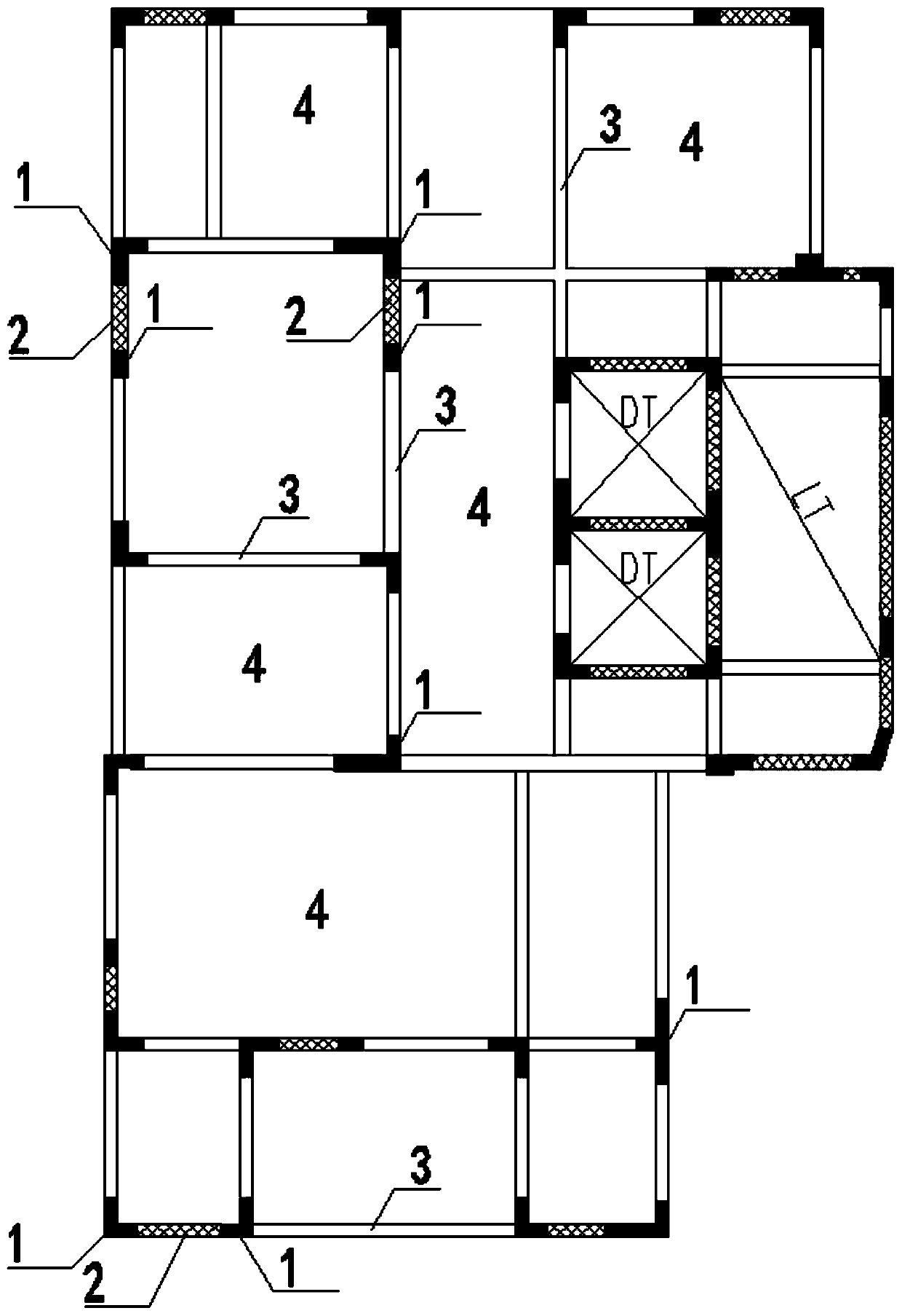
[0064] Such as Figure 1-12 As shown, the prefabricated part provided by the present invention includes a column formwork 11 and a steel skeleton 12. The steel framework 12 is arranged in the column formwork 11 and connected with the column formwork 11. On the column formwork 11 A beam connection hole 111 communicating with the inside of the structural beam 3 is provided at a position corresponding to the structural beam 3 .

[0065] The prefabricated part of this application has completed most of the template and steel bar installation processes, which reduces the weight of the components to be transported while maintaining the advantages of factory production, thereby reducing transportation costs and hoisting costs, and promoting the promotion of prefabricated buildings , the column formwork 11 on the prefabricated part has airtight constraint effect on the concrete, can improve the compressive strength of the concrete, is beneficial to reduce the section of the column and ...

Embodiment 2

[0076] Such as Figure 1-11 As shown, this embodiment discloses a structural column 1, which includes several sections of prefabricated parts as described in Embodiment 1, and also includes column cast-in-place parts. The prefabricated parts are vertically spliced ​​and connected to each other vertically. The column cast-in-place parts are concrete solidification parts poured in the connected prefabricated parts.

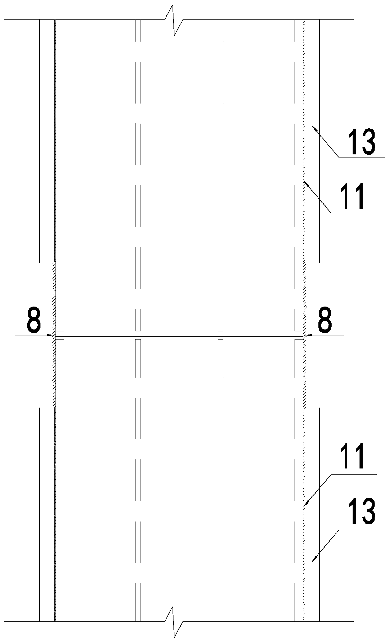
[0077] Such as figure 2 , 3 As shown, at the beginning, the two ends of the steel skeleton 12 respectively extend from the two ends of the column formwork 11 to the outside of the column formwork 11, and the vertical steel columns outside the prefabricated parts adjacent up and down The periphery of the bar 121 is provided with a connecting sleeve 8, and the connecting sleeve 8 communicates with the column mold sleeves 11 adjacent up and down.

[0078] In this embodiment, the connection set 8 is formed by welding the upper and lower adjacent column mold sets 11 ...

Embodiment 3

[0081] Such as figure 1 , 10 , 11, this embodiment discloses a shear wall 2, which includes a prefabricated wall skeleton 22 and the prefabricated part described in Embodiment 1. The prefabricated wall skeleton 22 is cross-shaped and arranged on adjacent prefabricated parts In between, the ends of the prefabricated wall frame 22 are connected to the prefabricated parts; post-cast walls with the prefabricated wall frame 22 as the skeleton are post-cast between the adjacent prefabricated parts.

[0082] In this embodiment, the shear wall 2 further includes at least two prefabricated wall panels 21, the prefabricated wall panels 21 are arranged parallel to each other, and the two ends of the prefabricated wall panels 21 are respectively connected to the adjacent prefabricated parts ; The prefabricated wall skeleton 22 is set in the wall space surrounded by the prefabricated wall panels 21 and the prefabricated parts, and the post-cast wall body 23 is a solidification element pou...


PUM


Abstract

The invention relates to the technical field of prefabricated buildings, in particular to a prefabricated member, a structure column, a shear wall, a semi-prefabricated building structure and a construction method thereof. The prefabricated member comprises a columnar die sleeve and a steel framework, wherein the steel framework is arranged in the columnar die sleeve and is connected with the columnar die sleeve; and a structural opening connected with a beam is formed in the columnar die sleeve. The prefabricated member is produced in a factory, and the mounting procedure of most die plates and rebars is finished; and in addition, a cavity is formed in the columnar die sleeve, so that the advantages of keeping industrialized production while greatly reducing the weight of the prefabricated member are realized. The semi-prefabricated building structure comprises the structure column and / or the shear wall, a prefabricated groove beam and a prefabricated floorslab. After assembling, concrete is synchronously poured in the cavity, and a beam and plate overlapping layer in the prefabricated member to form a structural system with excellent integrality. The prefabricated member has theadvantages of being convenient in construction, reliable in connection, reduced in cost, and similar to stress of the existing structural system and facilitates popularization of a prefabricated building.

Description

technical field [0001] The invention relates to the technical field of prefabricated buildings, in particular to a prefabricated part, a structural column, a shear wall, a semi-fabricated building structure and a construction method thereof. Background technique [0002] At present, prefabricated buildings have become a new development direction of the construction industry due to the factory production of prefabricated parts. However, one of the reasons why it is difficult to promote prefabricated buildings includes the excessive weight of prefabricated parts. The weight of prefabricated parts cast by concrete can reach hundreds of tons. High-weight prefabricated parts have extremely high requirements for transportation vehicles, transportation roads, and hoisting equipment. The substantial increase in the construction cost of prefabricated buildings makes it difficult to promote prefabricated buildings. Contents of the invention [0003] In order to overcome the deficie...

Claims


Application Information

Patent Timeline
Patent Type & Authority Applications(China)
IPC IPC(8): E04B1/04E04B1/20E04B1/21
CPCE04B1/04E04B1/20E04B1/21
Inventor 李胜强
Owner GUANGDONG UNIV OF PETROCHEMICAL TECH
Learn More