Horizontal projectile motion law demonstration instrument
What is Al technical title?
Al technical title is built by PatSnap Al team. It summarizes the technical point description of the patent document.
A technology of movement rules and demonstrators, which is applied in the direction of instruments, educational tools, teaching models, etc., can solve the problems that are not conducive to students' understanding and mastering, and achieve the effect of strong participation of students, reducing difficulty and obvious effect
Inactive Publication Date: 2020-05-01
HUAIHUA UNIV
View PDF0 Cites 0 Cited by
Summary
Abstract
Description
Claims
Application Information
AI Technical Summary
This helps you quickly interpret patents by identifying the three key elements:
Problems solved by technology
Method used
Benefits of technology
Problems solved by technology
[0002] In the second section of the fifth chapter of the high school "Physics" Compulsory II (PEP Edition) - "Platform Throwing Motion", students need to understand that the two sub-movements of the flat throwing motion can be equivalent to the vertical direction The free fall motion in the horizontal direction and the uniform linear motion in the horizontal direction, the existing experimental instruments in the book only involve the demonstration of the free fall motion in the vertical direction, and it is all based on the impact sound of two small balls falling to the ground to judge whether they land at the same time, but The ball will not stop moving immediately after it hits the ground, and there will be several consecutive impact sounds. Because there is no exact time display, some students will question it, which is not conducive to students' understanding and mastering the key points of this knowledge
Method used
Image
Click on the blue label to locate the original text in one second.
Reading with bidirectional positioning of images and text.
Examples
Embodiment Construction
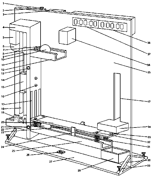
[0009] The invention provides a demonstration instrument for the movement law of flat throwing, which has clever control circuit design, simple operation, easy understanding, and can intuitively demonstrate the isochronism of split movement, and obtain the movement law of flat throwing movement through verification.
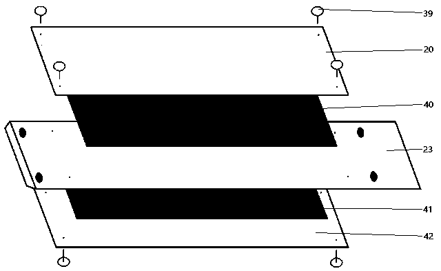
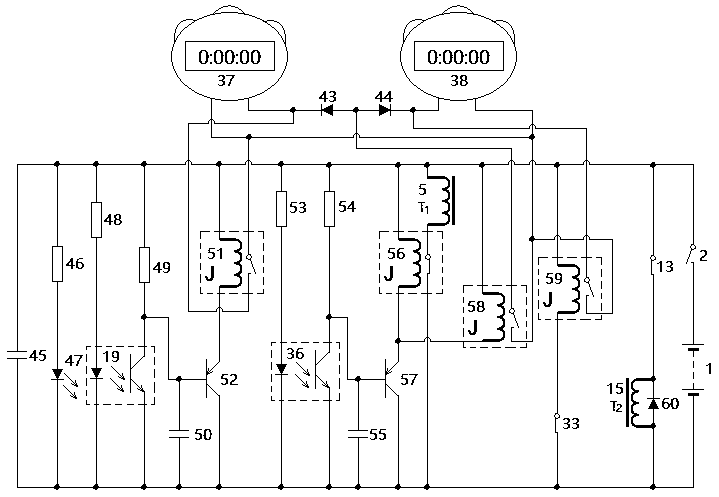
[0010] Such as Figure 1 to Figure 3 As shown, the device of the present invention includes a power supply 1, a main switch 2, a control circuit box 3, an inverted "L" shaped wooden frame 4, a second electromagnetic magnet 5, a third small ball 6, a push plate 7, and a first spring 8 , fixed pulley 9, first small ball 10, string 11, first slide rail 12, No. 1 switch 13, iron sheet 14, first electromagnetic magnet 15, screw 16, empty slot 17, partition 18, second Photoelectric switch 19, upper white paper 20, second small ball 21, adjusting nut 22, inverted trapezoid spring plate 23, barb 24, second slide rail 25, spirit level 26, bottom plate 27, storage box 28, ...
PUM
Abstract
For better verifying the motion law of horizontal projectile motion, the invention provides a horizontal projectile motion law demonstration instrument mainly composed of a power supply, a control circuit box, an inverted L-shaped wooden frame, an electromagnetic magnet, small balls, a spring, a sliding rail, a photoelectric switch, an inverted trapezoidal elastic plate, a wood plate, timers, carbon paper, white paper, a resistor, a capacitor, a chip, a relay, a diode and the like. Electromagnetic magnet, photoelectric switch and relay design circuits are used for controlling the three small balls to simultaneously start to move. The two timers are started at the same time and separately time to display the exact time; the horizontal projectile motion and the vertical sub-motion are compared, the horizontal projectile motion and the horizontal sub-motion are compared through traces left on the white paper by the carbon paper when the inverted trapezoidal elastic plate is impacted by the small balls, the experimental circuit design is ingenious, the difficulty of obtaining experimental data is reduced, the operability of experiments is improved, and the development of experimental exploration teaching is better facilitated.
Description
technical field [0001] The invention relates to a middle school physics teaching and experimental instrument, in particular to an instrument for demonstrating the law of flat throwing motion. Background technique [0002] In the second section of the fifth chapter of the high school "Physics" Compulsory II (PEP Edition) - "Platform Throwing Motion", students need to understand that the two sub-movements of the flat throwing motion can be equivalent to the vertical direction The free fall motion in the horizontal direction and the uniform linear motion in the horizontal direction, the existing experimental instruments in the book only involve the demonstration of the free fall motion in the vertical direction, and it is all based on the impact sound of two small balls falling to the ground to judge whether they land at the same time, but After the ball hits the ground, it will not stop immediately, and there will be several consecutive impact sounds. Because there is no exact...
Claims
Application Information
Patent Timeline
Application Date:The date an application was filed.
Publication Date:The date a patent or application was officially published.
First Publication Date:The earliest publication date of a patent with the same application number.
Issue Date:Publication date of the patent grant document.
PCT Entry Date:The Entry date of PCT National Phase.
Estimated Expiry Date:The statutory expiry date of a patent right according to the Patent Law, and it is the longest term of protection that the patent right can achieve without the termination of the patent right due to other reasons(Term extension factor has been taken into account ).
Invalid Date:Actual expiry date is based on effective date or publication date of legal transaction data of invalid patent.