
Loop antenna and antenna oscillator

An antenna vibrator and strip technology, which is applied to loop antennas, antennas, antenna supports/installation devices, etc., can solve the problems of inconvenient transportation of short-wave loop antennas, and achieve the effect of convenient transportation and space saving.

Pending Publication Date: 2020-05-01
HEBI XINYUAN ELECTRONIC CO LTD
View PDF0 Cites 0 Cited by
  • Summary
  • Abstract
  • Description
  • Claims
  • Application Information

AI Technical Summary

Problems solved by technology

[0003] The purpose of the present invention is to provide a loop antenna, which is used to solve the technical problem of inconvenient transportation of short-wave loop antennas in the prior art

Method used


Image

  • Loop antenna and antenna oscillator
  • Loop antenna and antenna oscillator

Examples


Embodiment Construction

[0029] Embodiments of the present invention will be further described below in conjunction with the accompanying drawings.

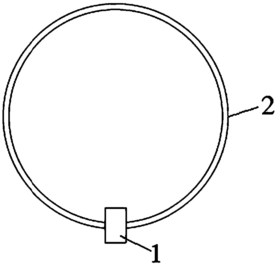
[0030] Embodiments of the loop antenna of the present invention, such as figure 1 As shown, the loop antenna includes an antenna base 1 and a ring-shaped antenna rod 2 fixed on the antenna base 1. The antenna rod 2 is formed by sequentially inserting and splicing a plurality of antenna vibrators. In this embodiment, there are four antenna vibrators. The head end of one of the adjacent two antenna elements is plugged and fixed with the tail end of the other. The first and last ends of the spliced ​​antenna rod 2 are respectively fixed on both sides of the antenna base 1 .

[0031] Such as figure 2 As shown, the antenna vibrator includes a bendable strip-shaped substrate, and the strip-shaped substrate includes an elastically bendable non-metallic inner rod 4, and the material of the non-metallic inner rod 4 in this embodiment is carbon fiber. The two ...


PUM


Abstract

The invention relates to a loop antenna and an antenna oscillator. The antenna oscillator comprises a bendable strip-shaped base body, wherein the strip-shaped base body comprises an elastic bendablenon-metal inner rod and a metal shielding layer wrapping an outer peripheral surface of the non-metal inner rod, the outer peripheral surface of the metal shielding layer is provided with a protectivelayer, two ends of the non-metal inner rod are connected with metal connectors used for connecting two antenna oscillators in series, and two ends of the metal shielding layer are electrically connected with the metal connectors on the corresponding sides in series. The antenna oscillator adopts the bendable strip-shaped base body, so the shape of the antenna oscillator is adjustable, the antennaoscillator can be changed into a line shape during transportation, the space is saved, and transportation is convenient.

Description

technical field [0001] The invention relates to a loop antenna and an antenna vibrator. Background technique [0002] As a signal transceiving device, the antenna is mainly used to convert the radio frequency power fed by the transmitter into electromagnetic wave energy radiated to the designated space, or convert the electromagnetic wave energy propagated in the designated space into radio frequency power and send it to the receiver. The antenna is mainly composed of the antenna base and the antenna vibrator fixed on the antenna base. At present, according to the different frequencies of the electromagnetic waves received and emitted by the antenna, the antenna can be divided into long-wave antennas and short-wave antennas. The frequency of electromagnetic waves received and emitted by the short-wave antenna is between 3 and 30 MHz, and the corresponding wavelength is between 10 and 100 m. In order to achieve the best transmitting and receiving effect, the length of the an...

Claims


Application Information

Patent Timeline
Patent Type & Authority Applications(China)
IPC IPC(8): H01Q1/50H01Q1/38H01Q1/40H01Q1/12H01Q7/00
CPCH01Q1/12H01Q1/38H01Q1/40H01Q1/50H01Q7/00
Inventor 王新纪龚震陈汉超黄彦平李玉善钱东方徐文亮
Owner HEBI XINYUAN ELECTRONIC CO LTD
Learn More