Transformer substation monitoring method

A substation monitoring and substation technology, applied in the field of substation monitoring, can solve problems such as omission, dangerous high-voltage equipment, and lack of protection functions, etc., to achieve strong practicability, ensure safe operation, and broad application prospects

Inactive Publication Date: 2020-05-01
NINGDE POWER SUPPLY COMPANY STATE GRID FUJIAN ELECTRIC POWER +1
View PDF4 Cites 0 Cited by
  • Summary
  • Abstract
  • Description
  • Claims
  • Application Information

AI Technical Summary

Problems solved by technology

For the first two methods, because there is no bionic compound eye design for the operation characteristics and structure of high-voltage equipment in substations, they cannot simultaneously have the wide, clear, and far functions of visible light, infrared, and ultraviolet light, and may be missed or not timely and accurate in actual use. Detect heating and discharge faults of electric high-voltage equipment, as well as the detection of the correct position of opening and closing of the knife switch; it may also miss or fail to find that the staff crossed the red line in time, or dangerously approached the live high-voltage equipment in operation, endangering power production life safety and grid equipment safety
The inspection robot can only conduct mobile inspections of the high-voltage power equipment in the station according to the route and time, and cannot effectively monitor the large-scale power equipment of the whole station continuously for 24 hours, and it is even more helpless for the equipment with traffic obstacles.
In addition, the above three technical solutions do not have protection functions. When a fault is detected in the power equipment, an alarm signal can only be sent out, or the maintenance personnel can be notified to deal with it. It is impossible to transfer the faulty equipment through automatic control of the backup interval for serious faults. load, reduce the pressure on faulty equipment, and maintain a smooth transition of faulty equipment before maintenance personnel arrive

Method used


Image

  • Transformer substation monitoring method
  • Transformer substation monitoring method
  • Transformer substation monitoring method

Examples


Embodiment Construction

[0018] The present invention will be further described in detail below in conjunction with the accompanying drawings and specific embodiments.

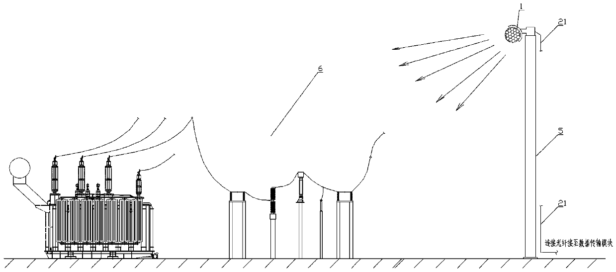
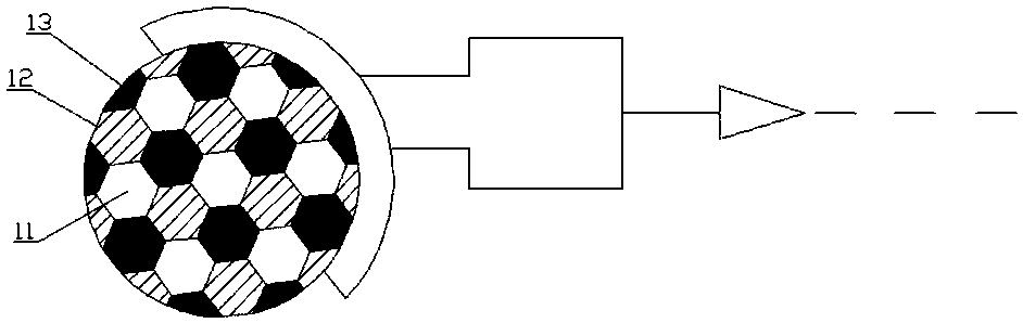
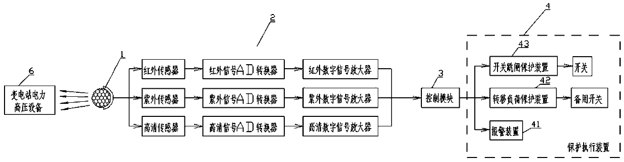
[0019] The present invention provides a substation monitoring method aiming at the operation mode and its own characteristics of the electric high-voltage equipment in the substation, such as Figure 1~3 As shown, a compound eye combination probe 1 composed of multiple miniature infrared probes 11, miniature ultraviolet probes 12 and miniature high-definition probes 13 is installed on the monitoring pole in the substation to monitor each electric high-voltage equipment 6 in the substation. The probes detect overheating faults in the operation of high-voltage electric equipment. The probes are arranged on the compound eye combination probe according to the regular hexagonal interval of the bionic compound eye. The discharge fault of the high-voltage electric equipment is detected by the miniature ultraviolet probe, and the opening and c...


PUM


Abstract

The invention relates to a transformer substation monitoring method. According to the method, a compound eye combined probe consisting of a plurality of micro infrared probes, micro ultraviolet probesand micro high-definition probes is arranged on a monitoring vertical rod in a transformer substation; each power high-voltage device in the transformer substation is monitored; the micro infrared probe is used for detecting an overheat fault in operation of the the power high-voltage device; the discharge fault of the power high-voltage device is detected through the micro ultraviolet probe; whether opening and closing of the isolation switch are in correct positions is detected through the micro high-definition probe; whether a worker crosses a red line or not and whether danger is close tothe high-voltage device or not is judged; all probes in the compound eye combined probe are electrically connected with the control module through the corresponding data transmission modules respectively; and the protection execution device is controlled to work through the control module so as to carry out corresponding fault protection. The method is beneficial to effective monitoring and faultprotection of the power high-voltage equipment in the transformer substation.

Description

technical field [0001] The invention belongs to the technical field of substation monitoring, and in particular relates to a substation monitoring method. Background technique [0002] The existing non-contact monitoring technology solutions for high-voltage power equipment in substations mainly include the following three methods: 1) Staff carry infrared and ultraviolet detection instruments to detect overheating and discharge faults of high-voltage power equipment in substations; 2) Install ordinary visible light probes to detect The high-voltage power equipment and staff in the substation are visually monitored; 3) The inspection robot conducts mobile inspections on the high-voltage power equipment in the station. For the first two methods, because there is no bionic compound eye design for the operation characteristics and structure of high-voltage equipment in substations, they cannot simultaneously have the wide, clear, and far functions of visible light, infrared, and...

Claims


Application Information

Patent Timeline
Patent Type & Authority Applications(China)
IPC IPC(8): H02H1/00H02H7/22H02J13/00G01R31/327
CPCH02H1/0007H02H1/0069H02H7/22G01R31/3275Y04S10/20Y04S40/126Y02E60/00
Inventor 阮肇华陈玉树林晓铭梁宏池任乔林林鸿伟郑东升陈锦植连鸿松涂承谦李志源黄兰南陈华忠黄凌
Owner NINGDE POWER SUPPLY COMPANY STATE GRID FUJIAN ELECTRIC POWER
Why Eureka
Try Eureka