
A high-efficiency drilling equipment with special-shaped flywheel automatic loading and unloading

A technology of automatic loading and unloading and drilling equipment, applied in metal processing equipment, perforation tools, feeding devices, etc., can solve the problems of lack of automatic loading and unloading equipment, inaccurate positioning accuracy, low product production efficiency, etc., to improve equipment. Production efficiency, improve work efficiency, and the effect of efficient loading and unloading operations

Active Publication Date: 2022-02-08
南昌联达机械有限公司
View PDF6 Cites 0 Cited by
  • Summary
  • Abstract
  • Description
  • Claims
  • Application Information

AI Technical Summary

Problems solved by technology

[0005] The technical problem to be solved by the present invention is to provide a high-efficiency drilling equipment for automatic loading and unloading of special-shaped flywheels. This technical solution solves the problem of lack of automatic loading and unloading equipment for special-shaped flywheel parts in automobiles, insufficient positioning accuracy, and low production efficiency. And other issues

Method used


Image

  • A high-efficiency drilling equipment with special-shaped flywheel automatic loading and unloading
  • A high-efficiency drilling equipment with special-shaped flywheel automatic loading and unloading
  • A high-efficiency drilling equipment with special-shaped flywheel automatic loading and unloading

Examples


Embodiment Construction

[0031] In order to make the objects, technical solutions and advantages of the present invention, the present invention will be described in detail below with reference to the accompanying drawings and examples. It is to be understood that the specific embodiments described herein are intended to explain the present invention and is not intended to limit the invention.

[0032] In the description of the present invention, it is to be desirable in terms of the term "center", "upper", "lower", "left", "right", "front", "post", "vertical", "horizontal", The orientation of the "internal", "outside", etc. is based on the orientation or positional relationship shown in the drawings, which is merely intended to describe the present invention and simplified description, rather than indicating or implying that the device or component must have The specific orientation is constructed and operated in a specific orientation, so it is not understood to limit the limitations of the invention. M...


PUM


Abstract

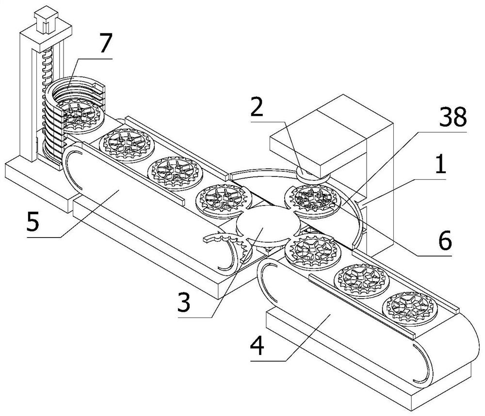
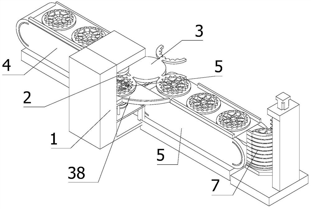
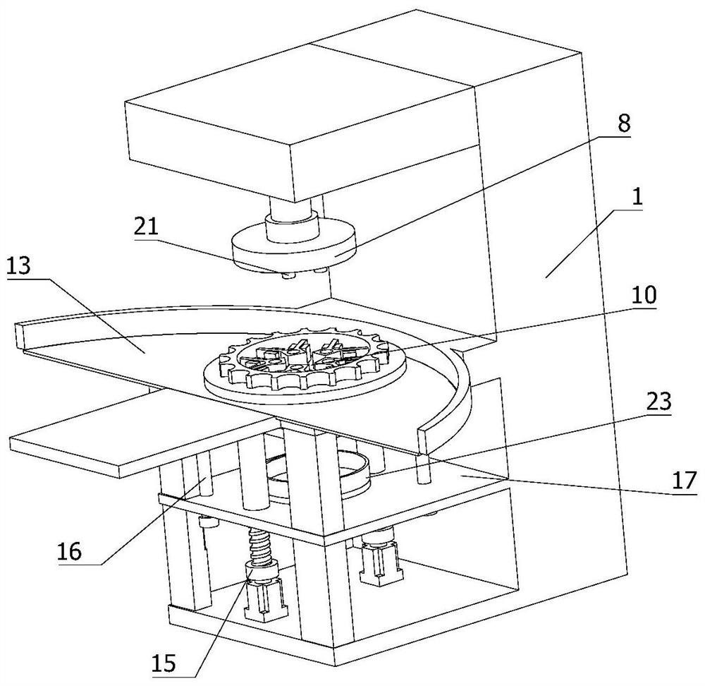
The invention relates to the field of mechanical processing, in particular to a high-efficiency drilling equipment for automatic loading and unloading of special-shaped flywheels, including a special-shaped flywheel, a frame, a punching assembly, a rotating loading and unloading assembly, a first conveyor belt, and a second conveyor belt , positioning components and stacking components, the top of the frame is provided with a horizontal working platform, the output end of the punching component is fixedly installed with a horizontal lifting plate, the punching component includes an upper mold that can be lifted vertically, and the positioning component includes The lower mold can be vertically lifted and matched with the upper mold. The top of the working platform is provided with a circular avoidance for the lower mold to pass through. The rotary loading and unloading assembly includes a rotatable rotating disk, and the outer wall of the rotating disk is uniformly fixed and connected. There are four arc-shaped material transfer plates. The high-efficiency drilling equipment shown in the present invention realizes fully automated loading and unloading operations, greatly reduces the labor intensity of workers, improves work efficiency, and can complete stamping operations at one time, which greatly simplifies Steps.

Description

Technical field [0001] The present invention relates to the field of machining, and in particular, to a high-efficiency drilling apparatus for automatic upper and lower materials of a shaped flywheel. Background technique [0002] Automotive parts as the basis of the automotive industry is the necessary factors that support the continued healthy development of the automobile industry. In particular, the current automotive industry is speaking, such as the autonomous development and innovation of the fire, and needs a strong part system for support. The autonomy of the whole vehicle needs the basis of parts, and the independent innovation of components has a powerful driving force in the development of the vehicle industry. They are interacting, interacting, no autonomous brands, strong parts system. The research and development of innovation ability is difficult to burst, there is no support for strong parts system, and the self-owned brands will be unpleasant. [0003] The shape...

Claims


Application Information

Patent Timeline
Patent Type & Authority Patents(China)
IPC IPC(8): B21D28/32B21D28/34B21D43/00B21D43/12B21D43/20B21D45/00
CPCB21D28/32B21D28/34B21D43/12B21D43/003B21D43/20B21D45/003
Inventor 张武军
Owner 南昌联达机械有限公司
Learn More