
LED module maintenance device

A technology of LED modules and maintenance devices, applied in auxiliary devices, metal processing, metal processing equipment, etc., can solve the problems of strong repeatability, cumbersome operation, and single content.

Active Publication Date: 2020-05-05
SHENZHEN LAMP TECH +1
View PDF5 Cites 9 Cited by
  • Summary
  • Abstract
  • Description
  • Claims
  • Application Information

AI Technical Summary

Problems solved by technology

[0006] In view of this, the purpose of the present invention is to provide a LED module maintenance device to solve the problems of cumbersome operation, strong repeatability and single content encountered in the fault maintenance process of the existing LED module patch lamp. Simple structure, easy to operate, simplify the maintenance work of LED lamp surface, reduce maintenance workload and maintenance cost

Method used


Image

  • LED module maintenance device
  • LED module maintenance device
  • LED module maintenance device

Examples


Embodiment Construction

[0039] In order to make the technical problems, technical solutions and beneficial effects to be solved by the present invention clearer and clearer, the present invention will be further described in detail below in conjunction with the accompanying drawings and embodiments. It should be understood that the specific embodiments described here are only for explaining the present invention, and are not intended to limit the present invention.

[0040] In the following description, use of suffixes such as 'module', 'part' or 'unit' for denoting elements is only for facilitating description of the present invention and has no specific meaning by itself. Therefore, 'module', 'part' or 'unit' may be used in combination.

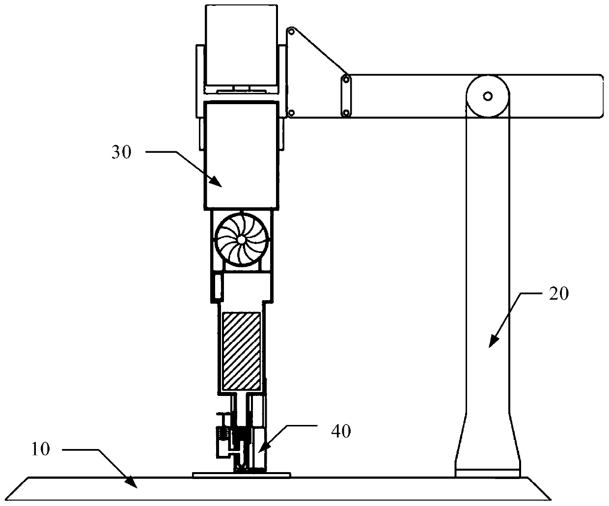
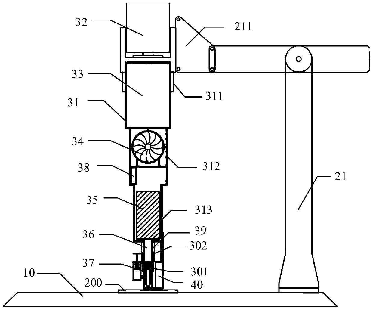
[0041] In one embodiment, such as figure 1 As shown, the present invention provides a LED module maintenance device, which includes: a clamping base 10, a calibration table 20, a maintenance device 30, and a feeding device 40; wherein:

[0042] The clamping base...


PUM


Abstract

The invention discloses an LED module maintenance device. The device comprises a clamping base, a correction table and a maintenance device. The clamping base is used for fixing and bearing a faulty LED module and the correction table; the correction table is used for conveying the maintenance device to a fault lamp bead of the LED module; the maintenance device is fixedly installed on the correction table and used for generating hot air and conveying the hot air to the LED module, so that soldering tin for soldering the faulty lamp beads on the LED module is melted, and the faulty lamp beadsare adsorbed and detached. Through the embodiment, the whole device is simple in structure and simple and convenient to operate, the LED lamp surface maintenance work is simplified, and the maintenance workload and the maintenance cost are reduced.

Description

technical field [0001] The invention relates to the field of display screen maintenance, in particular to an LED module maintenance device. Background technique [0002] The maintenance of the lamp surface is based on the maintenance requirements of the LED (Light Emitting Diode, light-emitting diode) patch lamp. Assist in the maintenance of LED patch lights. Furthermore, the operation of changing the LED lamp bead is performed automatically. [0003] Currently, LED (Light Emitting Diode, Light Emitting Diode) lamp surfaces may experience various failures during use, such as light drop, dead light, poor contact, and the like. At present, the processing method for the above faults is generally to disassemble the faulty LED module. After judging that the lamp bead needs to be reinforced or replaced, use a hot air gun to blow the solder of the faulty lamp bead, and then use tweezers to remove it. Take away the faulty lamp bead, and then put the lamp bead to be replaced with ...

Claims


Application Information

Patent Timeline
IPC IPC(8): B23K3/00B23K3/08
CPCB23K3/00B23K3/08
Inventor 王朝朱卫强
Owner SHENZHEN LAMP TECH
Learn More