Protection device with efficient heat dissipation function for electrical equipment

A technology for electrical equipment and protection devices, applied in substation/distribution device housing, substation/switchgear cooling/ventilation, electrical components, etc. Achieve the effect of improving air cooling effect, reducing evaporation rate and enhancing heat dissipation capacity

Inactive Publication Date: 2020-05-05
XIAN YONGXIN TECH CO LTD
View PDF3 Cites 2 Cited by
  • Summary
  • Abstract
  • Description
  • Claims
  • Application Information

AI Technical Summary

Problems solved by technology

[0004] 1. Most of the general electrical equipment is installed outdoors, and its heat dissipation ability is poor. Especially in high temperature weather, the electrical equipment cannot get good heat dissipation, which will easily cause damage to the internal circuit and bring great inconvenience to the use.
[0005] 2. The existing electrical equipment is equipped with a heat dissipation structure to protect the electrical equipment, and the rainwater is used to cool the electrical equipment, but the collected rainwater will evaporate quickly. can't play a big role

Method used


Image

  • Protection device with efficient heat dissipation function for electrical equipment
  • Protection device with efficient heat dissipation function for electrical equipment
  • Protection device with efficient heat dissipation function for electrical equipment

Examples


Embodiment 1

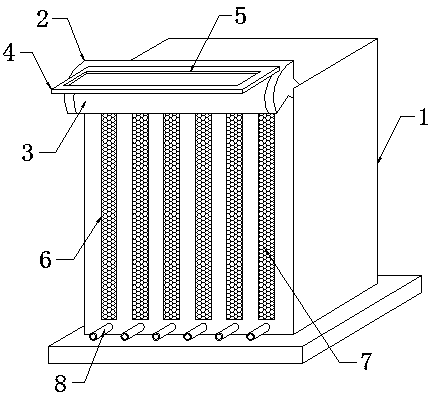
[0028] according to figure 1 As shown, it includes an electrical equipment casing 1, and one side of the top of the electrical equipment casing 1 is fixedly connected with a rain collecting box 2, and the front of the rain collecting box 2 is slidably connected with an arc-shaped shroud 3, which can shield the rainwater inside the rain collecting box 2 , greatly reducing the speed of rainwater evaporation, prolonging the time for rainwater cooling and cooling, one side of the top of the arc shutter 3 is fixedly connected with a power plate 4, the top of the power plate 4 is dug with a rain groove 5, and the back of the electrical equipment casing 1 is dug with a A plurality of strip-shaped grooves 6, the inner wall of the strip-shaped groove 6 is fixedly connected with a dust-proof net 7, and the outside air enters the inside of the electrical equipment casing 1 through the dust-proof net 7, reducing the possibility of dust entering, and the top inner wall of the electrical equ...

Embodiment 2

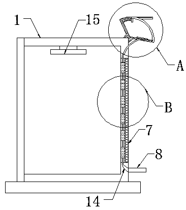
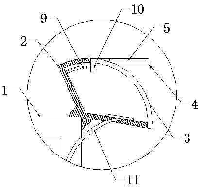
[0030] On the basis of embodiment one, according to image 3 As shown, one side of the bottom end of the arc shutter 3 is fixedly connected with a fixed plate 10, a side wall of the fixed plate 10 is fixedly connected with a pair of tension springs 9, and one end of a pair of tension springs 9 away from the fixed plate 10 is connected with the set The inner wall of the rain box 2 is fixedly connected, and when the rainwater inside the rain gutter 5 evaporates first, the pulling force of the tension spring 9 drives the arc shutter 3 to reset, and the rainwater inside is shielded and protected.

[0031] Wherein, the bottom end of the inner wall of the rain collecting box 2 is fixedly connected with a filter screen, and the position of the filter screen is directly opposite to the position of the upper connecting pipe 11, and the rainwater entering the upper connecting pipe 11 is filtered to reduce the probability of dust and foreign matter entering, Prevent cold water pipe 12 an...

Embodiment 3

[0033] On the basis of embodiment one and embodiment two, according to Figure 4 As shown, a plurality of cold water pipes 12 are equidistantly fixedly connected to the side wall of the dustproof net 7, and are fixedly connected by a communication pipe 13 between the plurality of cold water pipes 12. The diameter of the communication pipe 13 is less than the diameter of the cold water pipe 12, and the communication pipe 12 13 can reduce the speed of rainwater flowing down and increase the cooling time of cold water. The cold water pipe 12 increases the flow of rainwater to ensure sufficient water cooling effect.


PUM


Abstract

The invention discloses a protection device with an efficient heat dissipation function for electrical equipment. The protection device comprises an electrical equipment housing. A rain collecting boxis fixedly connected to one side of the top end of the electrical equipment housing; the front surface of the rainwater collecting box is slidably connected with an arc-shaped shielding plate; one side of the top end of the arc-shaped shielding plate is fixedly connected with a power plate; a rain gutter is dug in the top end of the power plate; a plurality of strip-shaped grooves are formed in the back surface of the electrical equipment housing; and the inner walls of the strip-shaped grooves are fixedly connected with a dustproof net. According to the protection device with the efficient heat dissipation function for the electrical equipment, a plurality of cold water pipes are arranged to be matched with the communicating pipe, and after rainwater flows in, the rainwater can flow slowly, so that the water cooling effect is achieved, and the heat dissipation capacity of the electrical equipment is greatly enhanced; and by arranging the rainwater collecting box and the power plate,under the cooperation of the arc-shaped shielding plate and the extension spring, the arc-shaped shielding plate can be driven to slide downwards through the gravity and impact force of the rainwaterin rainy days, and the rainwater is collected.

Description

technical field [0001] The invention relates to a protection device for electrical equipment, in particular to a protection device for electrical equipment with efficient heat dissipation. Background technique [0002] Electrical equipment is a general term for generators, transformers, power lines, circuit breakers and other equipment in the power system. The important role played by electricity in our life and production cannot be ignored. It brings us great convenience and becomes our The production of vital energy in life. The most critical element in a power plant for the proper operation and delivery of electricity is the electrical equipment. [0003] In view of this, Chinese Patent No. CN208767624U proposes an anti-leakage protection device for electrical equipment to protect electrical equipment against leakage, and Chinese Patent No. CN207925904U proposes an insulation protection device for high and low voltage electrical equipment to protect the wires of electric...

Claims


Application Information

Patent Timeline
Patent Type & Authority Applications(China)
IPC IPC(8): H02B1/26H02B1/56H02B1/28
CPCH02B1/26H02B1/28H02B1/565
Inventor 范青鹏
Owner XIAN YONGXIN TECH CO LTD
Why Eureka
Try Eureka