Solar cell module electrical performance test lead device

A solar cell module, electrical performance testing technology, applied in electrical components, photovoltaic power generation, photovoltaic system monitoring and other directions, can solve problems such as increasing electrical performance testing time, increasing the contact resistance of conductive cores, and reducing operator experience. The effect of eliminating bad experience, reducing measurement deviation, and improving test efficiency

Pending Publication Date: 2020-05-05
陕西众森电能科技有限公司
View PDF0 Cites 1 Cited by
  • Summary
  • Abstract
  • Description
  • Claims
  • Application Information

AI Technical Summary

Problems solved by technology

[0004] In the prior art, the electrical performance testing process is as follows: the solar battery module is fed to a predetermined position, the tail cable connector of the solar battery module is manually connected to the lead connector of the electrical performance testing device, the electrical performance is tested, and the tail cable connector is manually pulled out, and the solar battery module is manually disconnected. Battery module discharge; each step in the above process is carried out in series, and the plugging and unplugging link takes nearly 10s, which significantly increases the time for electrical performance testing, and requires at least one person to curl up in a space less than 1m high on the backlight side of the solar cell module Inside, plugging and unplugging operations are carried out. Since the work on the production line is carried out continuously about 2,500 times a day, this seriously reduces the experience of operators and increases labor costs; and in the prior art, the end of the lead wire of the electrical performance testing device There are two male and female MC4 series connectors in each connector, and there is only one conductive core in each connector, which is responsible for the conduction of I and V electrical signals at the same time. The practice of conducting I and V electrical signals at the same time with one conductive core causes inaccurate measurement
After the solar cell generates electricity, the current starts from the positive electrode of the solar cell (the voltmeter is regarded as an open circuit), and flows into the negative electrode of the solar cell after passing through the positive electrode conductive core, the sampling resistor, the variable electronic load, and the negative electrode conductive core; There is a contact resistance between them, and there will be a voltage drop here, which will cause the measured result of the voltmeter of the solar cell to be lower than the terminal voltage of the solar cell; as the number of plugging and unplugging of the connector increases, the contact resistance of the conductive core will increase rapidly. Significant impact of solar cell electrical performance tests

Method used


Image

  • Solar cell module electrical performance test lead device
  • Solar cell module electrical performance test lead device
  • Solar cell module electrical performance test lead device

Examples


Embodiment 1

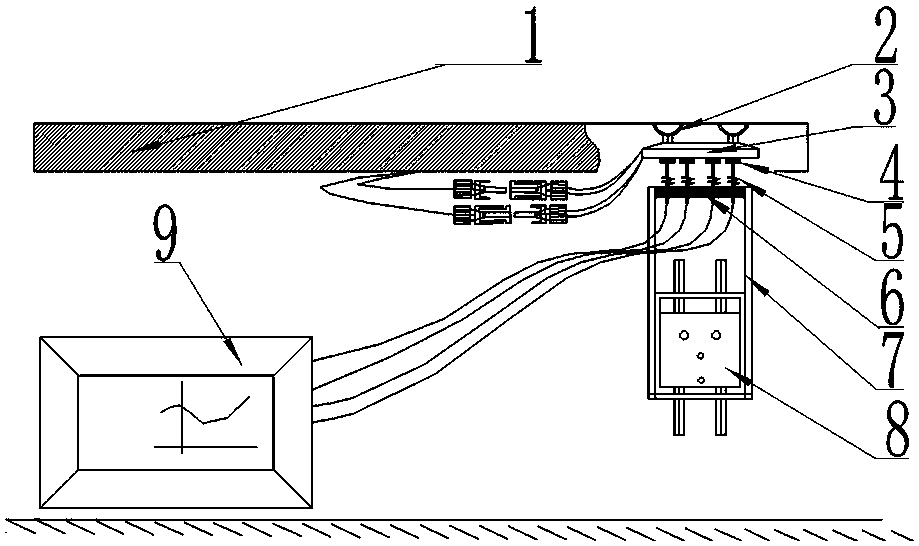
[0027] Solar cell module 1 electrical performance test lead device of the present invention, such as figure 1 Shown includes a piston module and a preset module; the piston module includes a support 6 that can reciprocate along a fixed track and an elastic conductive member 5; the elastic conductive member 5 is arranged on the aforementioned support 6; the elastic conductive member 5 and The electrical performance testing device 9 is electrically connected; the preset module includes a joint and a base 3; the base 3 is provided with a fixing device 2, and in this case, four air suction cups are selected as the fixing device 2; the bottom of the base 3 A conductive contact 4 is provided; the conductive contact 4 is electrically connected to the aforementioned connector. The support 6 is arranged on the top of the supporting mechanism 7, and the supporting mechanism 7 is arranged on the slider and its driving device 8. In this embodiment, the cylinder is selected as the slider a...

Embodiment 2

[0036] On the basis of Example 1, as Image 6 As shown, an implementation example of a pre-installed module uses a wedge 20 as the fixing device 2. The wedge 20 is located at one end of the base 3 and is integrally made with the base 3; the thicker part of the wedge 20 is thicker than the solar cell module 1 and its The distance between the flanging of the aluminum frame, and the thinner part of the wedge 20 is less than the distance between the solar cell module 1 and the flange of the aluminum frame; the base 3 of the pre-set module, with the end of the wedge 20, is pressed into the solar cell module 1 and its aluminum frame. Gaps in aluminum frame flanging, such as figure 1 as shown, figure 1 The flanging of the aluminum frame at the upper right corner will be clamped with the wedge 20 to fix the preset module.

[0037] The base 3 is provided with five conductive contacts 4 insulated from each other, four of which are arranged side by side and are used for the transmissio...

Embodiment 3

[0039] On the basis of Example 1, as Figure 7 As shown, an implementation case of a preset module adopts elastic clips as the fixing device 2; there are two elastic clips; the elastic clips are formed on the base 3 by springs 21, movable splints 22, shafts 23, etc.; The downward protrusion has a through hole on the protrusion, and the corresponding protrusion with the through hole on the base 3; the two through holes are passed through by the shaft 23, so that the movable splint 22 can surround the shaft 23, and the relative base 3 can Rotate within a certain range; such as Figure 7 As shown, the spring 21 is located between the movable splint 22 and the base 3, forcing the left end of the movable splint 22 to be raised, so that the right end of the movable splint 22 is engaged with the base 3; to prevent falling off;

[0040] During use, the function of fixing the preset module can also be achieved by engaging the flange of the aluminum frame of the solar cell module 1 wi...


PUM


Abstract

The invention provides a solar cell module electrical performance test lead device which belongs to the field of solar cell module electrical performance testing. The device is characterized in that the device comprises a piston module and a preset module; the piston module comprises a support capable of moving back and forth along a fixed track and elastic conductive parts; the elastic conductiveparts are arranged on the bracket in a mutual insulation manner; the preset module comprises a joint and a base; a fixing device is arranged at the top of the base; a conductive contact is arranged at the bottom end of the base; and the conductive contact is electrically connected with the joint. The lead between the solar cell module and the electrical performance test device is improved. Automatic testing of an electrical performance testing process is achieved through the preset module and the piston module. The testing efficiency is remarkably improved. The labor cost is reduced, and thebad experience that an operator curls up in a narrow space for a long time is avoided. By improving the structure of a conductive core in the joint, on the basis of being compatible and matched with an MC4 series joint on a tail cable of the solar cell module, inconvenience in testing is avoided, and testing is more accurate.

Description

technical field [0001] The invention belongs to the field of testing the electrical properties of solar cell components, in particular to a lead device for testing the electrical properties of solar cell components. Background technique [0002] A solar cell is a semiconductor sheet that can generate electricity through the photovoltaic effect. One side of the sheet is the positive electrode and the other side is the negative electrode. There are conductive metal grids or metal coatings on the positive and negative electrodes to collect current and voltage; solar cell components Generally, several solar cells are packaged in series or in parallel; generally there are two tail cables, one is positive and the other is negative; most tail cables use MC4 or imitation MC4 connectors. There are two types of joints, male and female, and there is only one conductive core inside. [0003] The electrical performance test of the solar cell is to irradiate the surface of the solar cell...

Claims


Application Information

Patent Timeline
Patent Type & Authority Applications(China)
IPC IPC(8): H02S50/10
CPCH02S50/10Y02E10/50
Inventor 刘皎黄国保冯云峰张鹤仙马文彬李超马红洲
Owner 陕西众森电能科技有限公司
Why Eureka
Try Eureka