
Rust removing device used for outer wall of square cylinder

A cylindrical and square technology, applied in the direction of grinding workpiece supports, grinding machines, metal processing equipment, etc., can solve the problems of few rust removal devices, lack of rust prevention treatment, low degree of automation, etc., to avoid interference and optimize rust removal effect. , to achieve the effect of automation

Active Publication Date: 2020-05-08
苏州创小二智能科技有限公司
View PDF7 Cites 11 Cited by
  • Summary
  • Abstract
  • Description
  • Claims
  • Application Information

AI Technical Summary

Problems solved by technology

[0009] Some manufacturers use iron sheets or other materials for processing in order to save costs when manufacturing square tubes, and lack sufficient anti-rust treatment. As a result, such products can be used normally at the initial stage of production, but after storage or use for a period of time, Due to the influence of the environment or other reasons, the outer wall will rust, which will affect its service life
[0010] However, in the prior art, there are few derusting devices for square cylinders, and the degree of automation is low; if the cylinder derusting equipment is directly used, due to its cross-sectional shape, it is easy to cause interference between the derusting parts and the square cylinder during switching. cause problems
[0011] Therefore, for the derusting work of the square cylinder, there is not yet a relatively complete mechanical equipment that can better solve the problem.

Method used


Image

  • Rust removing device used for outer wall of square cylinder
  • Rust removing device used for outer wall of square cylinder
  • Rust removing device used for outer wall of square cylinder

Examples


Embodiment 1

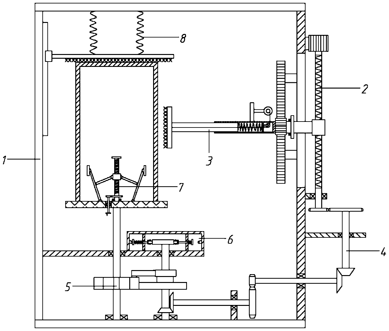
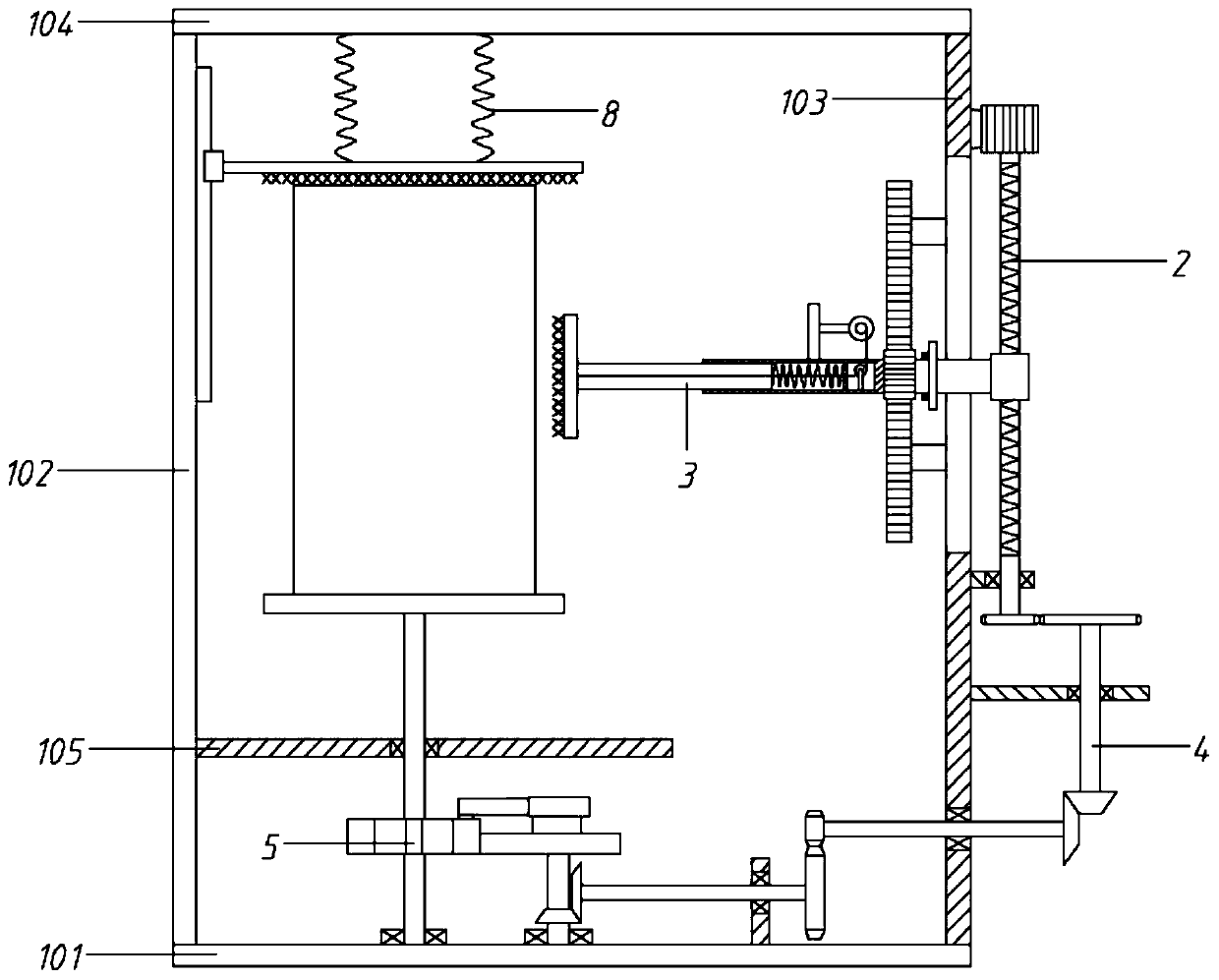
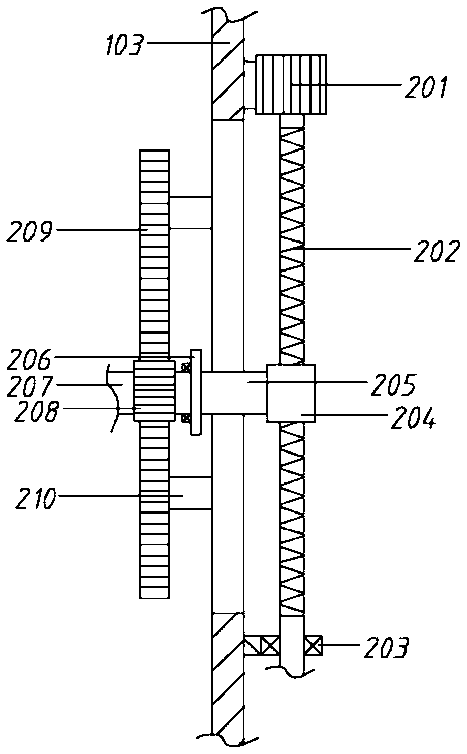
[0065] A derusting device for the outer wall of a square cylinder, comprising a frame 1, a driving component 2, a No. 1 derusting component 3, a No. 2 derusting component 8, a transmission component 4 and a rotating component 5;

[0066] The frame 1 includes a base 101, a left side plate 102, a right side plate 103, a top plate 104, and a support plate 105. The top of the right side plate 103 is connected by the top plate 104, and the right side of the lower section of the left side plate 102 is fixedly connected with a No. 1 support plate 105; the right side plate 103 is provided with the driving assembly 2; the base 101 is provided with the rotating assembly 5, the driving assembly 2 and the rotating assembly 5 is connected through the transmission assembly 4; the top of the rotating assembly 5 passes through the No. 1 support plate 105 and is provided with a rotating seat 506, which is used to place a square cylinder; the left side of the driving assembly 2 is provided with ...

Embodiment 2

[0068] A derusting device for the outer wall of a square cylinder, comprising a frame 1, a driving component 2, a No. 1 derusting component 3, a No. 2 derusting component 8, a transmission component 4 and a rotating component 5;

[0069] The frame 1 includes a base 101, a left side plate 102, a right side plate 103, a top plate 104, and a support plate 105. The top of the right side plate 103 is connected by the top plate 104, and the right side of the lower section of the left side plate 102 is fixedly connected with a No. 1 support plate 105; the right side plate 103 is provided with the driving assembly 2; the base 101 is provided with the rotating assembly 5, the driving assembly 2 and the rotating assembly 5 is connected through the transmission assembly 4; the top of the rotating assembly 5 passes through the No. 1 support plate 105 and is provided with a rotating seat 506, which is used to place a square cylinder; the left side of the driving assembly 2 is provided with ...

Embodiment 3

[0087] On the basis of embodiment 2,

[0088] It also includes an inner support assembly 7; the inner support assembly 7 includes a hand wheel 701, a No. 6 rotating shaft 702, a No. 5 gear 703, a No. 6 gear 704, a screw rod 705, an upper end plate 706, a threaded sleeve 707, a No. 1 rod 708, and a No. 2 rod 709 and inner support plate 710;

[0089] The top of the rotating seat 506 is coaxially provided with a screw 705, and the bottom end of the screw 705 is rotatably connected with the rotating seat 506 through a bearing; the top of the screw 705 is equipped with an upper end plate 706, and the threaded sleeve 707 is screwed on the screw 705; the second rod 709 is symmetrically arranged on On both sides of the screw rod 705, the bottom end of the second rod 709 is hinged with the rotating seat 506, and the top is hinged with an inner support plate 710; One end is hinged with the No. 2 rod 709; the No. 6 gear 704 is mounted on the screw 705, and the No. 6 gear 704 cooperates ...


PUM


Abstract

The invention relates to the technical field of rust removing of outer walls of square cylinders, in particular to a dust removing device used for the outer wall of a square cylinder. A servo motor isadopted for driving a reciprocating screw rod to rotate, a moving nut moves back and forth in the axial direction of the reciprocating screw rod, and an installation plate is driven to synchronouslymove through a first connecting rod; meanwhile, a first rotating shaft moves along with an installation plate, a driven gear and a rack act, the driven gear drives the first rotating shaft to rotate to act on a first rust removing assembly, and therefore the first rust removing assembly can also rotate while moving vertically, and the rust removing effect is optimized; a driving assembly also actson a rotating assembly through a transmission assembly, a sheave structure is adopted for completing face changing, comprehensive rust removing can be conveniently conducted on the outer wall of thesquare cylinder, during face changing, an electric wire collecting wheel is adjusted for conducting wire collecting, a rotary disc gets away from the square cylinder, and the phenomenon that the square cylinder interferes with the first rust removing assembly during rotation is avoided; and meanwhile, when the square cylinder rotates along with the rotating disc, the top of the square cylinder anda second rust removing assembly act, and rust removing is conducted.

Description

technical field [0001] The invention relates to the technical field of derusting the outer wall of a square cylinder, in particular to a derusting device for the outer wall of a square cylinder. Background technique [0002] The role of the cylinder is to provide the pressure space required by the process. It is one of the most important pressure components of the pressure vessel, and its inner diameter and volume often need to be determined by process calculations. Cylindrical barrel (ie cylinder) and spherical barrel are the most commonly used barrel structures in engineering. [0003] When the diameter of the cylinder is small (generally less than 500mm), the cylinder can be made of seamless steel pipe. At this time, there is no longitudinal weld on the cylinder; Press it into two semi-cylinders, and then weld the two together with a weld to form a full cylinder. [0004] In addition to cylinders and spherical cylinders, there is another common cylinder, the square cyli...

Claims


Application Information

Patent Timeline
IPC IPC(8): B24B27/033B24B41/06
CPCB24B27/033B24B41/067
Inventor 张巧云
Owner 苏州创小二智能科技有限公司
Learn More