Closed inner support type airless tire and production process thereof

An airless tire, supporting technology, applied in the direction of non-pneumatic tires, tire parts, tires, etc., can solve the problems of complex production process, not thick rubber tread, easy deformation of wheel spokes, etc., to achieve processing technology The effect of reasonable steps, weight reduction, and firm installation method

Pending Publication Date: 2020-05-08
浙江竤屹科技有限公司
View PDF4 Cites 2 Cited by
  • Summary
  • Abstract
  • Description
  • Claims
  • Application Information

AI Technical Summary

Problems solved by technology

For example, the patent whose authorization announcement number is CN106541785B, the patent whose authorization announcement number is CN106541784B, the patent whose authorization announcement number is CN106515313B and the patent whose authorization announcement number is CN106739817B all disclose a kind of airless tire in these four patents. Pneumatic tire comprises rubber tread and wheel spoke, and described rubber tread is sleeved on described wheel spoke, and described wheel spoke comprises wheel spoke outer circle, wheel spoke middle circle and wheel spoke inner circle, and described wheel spoke outer circle passes outer spoke and described wheel spoke The middle ring of the spoke is fixedly connected with the inner ring of the spoke through the inner spoke. The thickness of the rubber tread in this kind of airless tire is usually not thick, and the shock absorption and buffering performance of the airless tire mainly depends on the inner ring of the spoke. The spoke outer ring, the spoke middle ring and the spoke inner ring have the disadvantages that the spokes are easily deformed under pressure, and the production process is complicated. When driving on rainy roads, dirt is easy to enter the spokes, and it is not easy to clean.

Method used


Image

  • Closed inner support type airless tire and production process thereof
  • Closed inner support type airless tire and production process thereof
  • Closed inner support type airless tire and production process thereof

Examples


Embodiment Construction

[0039] The present invention will be further described in detail below in conjunction with the accompanying drawings and examples. The following examples are explanations of the present invention and the present invention is not limited to the following examples.

[0040] Example.

[0041] see Figure 1 to Figure 6 .

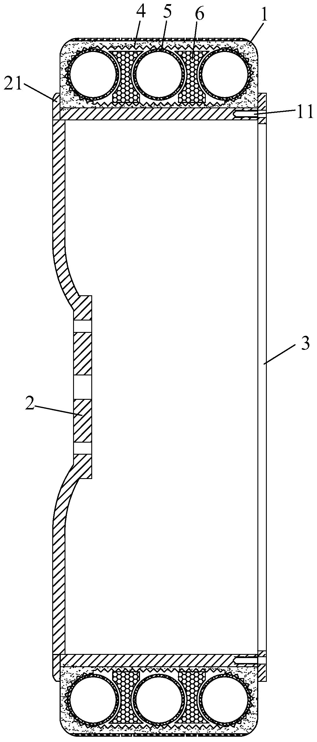
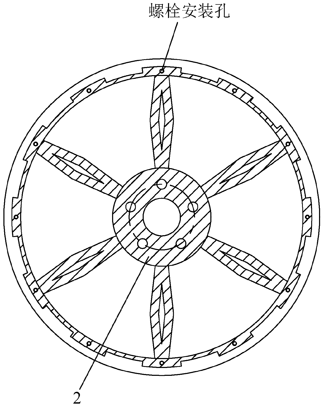
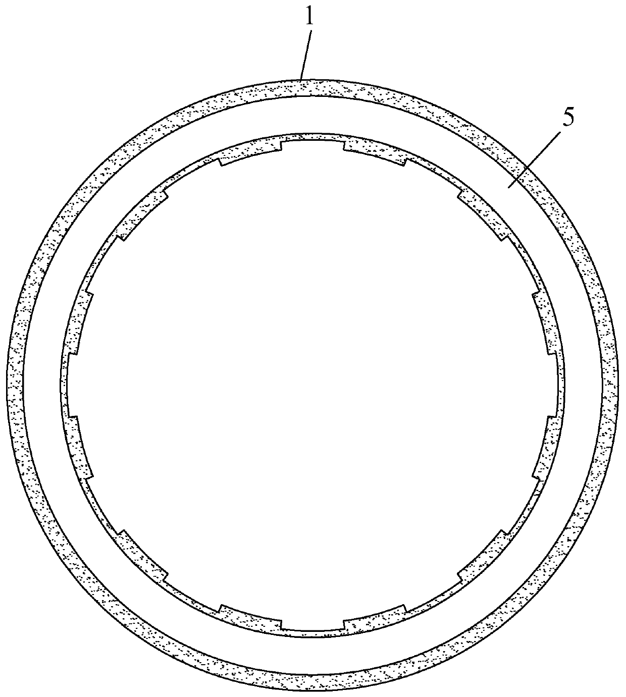
[0042] This embodiment is a closed inner support type airless tire, which includes a hub 2, an inner support member 5, an annular polyurethane foam 6 and a tire main body 1. Patterns are provided on the surface of the tire main body 1 in contact with the ground, the tire main body 1 is assembled on the hub 2, and the assembly joint surface of the two is provided with a concave-convex structure for positioning in the circumferential direction.

[0043] The inner support 5 is an annular member made of hollow polyurethane tubes connected end to end. The inner support 5 is placed in the tire main body 1 and surrounds the hub 2; at least two inner support members 5...


PUM

PropertyMeasurementUnit
sizeaaaaaaaaaa

Abstract

The invention discloses a closed inner support type airless tire and a production process thereof. The closed inner support type airless tire comprises a hub, inner support pieces and a tire main body, wherein the tire main body is assembled on the hub, the assembly joint surface of the two is subjected to circumferential positioning by arranging a concave-convex structure, the inner support pieceis an annular piece formed by connecting hollow polyurethane pipes end to end, and the inner support piece is arranged in the tire main body and surrounds the hub; the at least two inner support pieces are sequentially arranged in the axis direction of the tire main body. The tire main body is of a hollow structure formed by pouring polyurethane rubber, and the inner support piece is arranged inan inner cavity of the tire main body. The inner support piece, the annular polyurethane foaming body and the high-strength polyester gridding cloth are all poured into the inner cavity of the tire main body, the tire main body wrapped in a full-closed mode is close to an existing pneumatic tire in shape, and compared with the pneumatic tire, the airless tire is safe, reliable, high in strength, good in abrasion resistance, long in service life and suitable for large-scale automatic production and machining.

Description

technical field [0001] The invention relates to the technical field of tires, in particular to a closed inner support type airless tire and a production process thereof. Background technique [0002] At present, most of the tires used on vehicles are pneumatic tires. Pneumatic tires maintain the tire shape and obtain cushioning performance by filling compressed air into a closed space. It is difficult to maintain the original tire shape, which affects the safety of vehicles. In addition, there is a risk of tire blowout in pneumatic tires, especially in the event of a tire blowout on a vehicle traveling at high speed on the expressway, serious traffic accidents will occur. [0003] In order to solve this problem, airless tires are gradually being developed and put on the market. Airless tires are tires that do not rely on air to achieve support. They do not need to be inflated and are not afraid of punctures. , and can save a lot of rubber material. For example, the patent ...

Claims


Application Information

Patent Timeline
Patent Type & Authority Applications(China)
IPC IPC(8): B60C7/00B60B21/10B60B27/02B29C39/10B29L30/00
CPCB29C39/10B29L2030/006B60B21/10B60B27/02B60C7/00B60C2007/005
Inventor 夏文俊余承阳夏阳俊
Owner 浙江竤屹科技有限公司
Why Eureka
Try Eureka