A shaft expansion excavator and its construction method

A technology for roadheaders and shafts, which is applied in shaft equipment, sinking, earthwork drilling and mining, etc. It can solve problems such as the difficulty of shaft expansion and excavation, the long construction period of shafts, and the difficulty of shaft construction, so as to shorten the construction period of expansion and excavation , Improve the tunneling efficiency, the effect of high tunneling efficiency

Active Publication Date: 2021-09-24
CHINA RAILWAY ENGINEERING EQUIPMENT GROUP CO LTD
View PDF0 Cites 0 Cited by
  • Summary
  • Abstract
  • Description
  • Claims
  • Application Information

AI Technical Summary

Problems solved by technology

At present, the construction of the shaft is relatively difficult, and it is even more difficult to expand the shaft, resulting in a long construction period and low work efficiency

Method used


Image

  • A shaft expansion excavator and its construction method
  • A shaft expansion excavator and its construction method
  • A shaft expansion excavator and its construction method

Examples


Embodiment 2

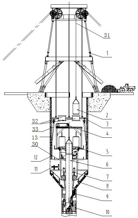
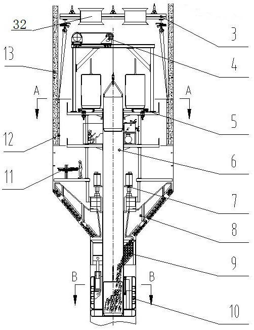
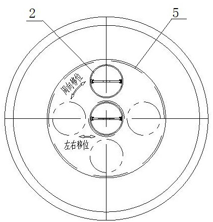
[0037] Example 2, such as Figure 5 As shown, a shaft expansion excavator, when the diameter of the original small-diameter shaft is not enough to place the lower propulsion device 10, the propulsion device can be arranged on the upper part of the cutter head and the main drive, and the rear part of the shoe cylinder is connected to the central column through Structure 17 is hinged, the front end of the shoe cylinder is hinged with the slider, the slider can slide up and down along the shoe plate, one end of the push cylinder is hinged with the shoe plate, and the other end is hinged with the central column connection structure. The shoe cylinder tightens the shoe plate, so that the shoe plate is pressed against the well wall rock, and the pushing cylinder generates pressure, which is transmitted to the center column, the main drive, and the conical cutterhead, and the pushing reaction force is transmitted from the shoe plate to the well wall rock. The slagging system include...

Embodiment 3

[0040] Embodiment 3: A construction method of the shaft expansion excavator as in Embodiment 2, the steps are as follows: S1: Excavation process: lift the main engine into the shaft hole to be expanded, and the cutter head system drives the cone The cutter head rotates to expand the shaft wall. During the expansion process, the gravity of the main engine and the pulling force of the propulsion device act together on the cutter head system to make the cutter head system move forward efficiently;

[0041] S2: Rock slag transportation: The rock mass is broken into rock slag under the action of the cutter head system, and the rock slag, under the disturbance of gravity and the rotation of the conical cutter head, moves closer to the center of the wellbore along the conical excavation face and slips into the center column Then the primary slag discharge mechanism of the slag discharge system lifts the bucket to the hoisting place of the secondary slag discharge mechanism, and the se...


PUM


Abstract

The invention discloses a shaft expansion excavator and a construction method thereof. The shaft expansion excavation machine includes a derrick and a main engine, the derrick is connected with the main engine through a winch mechanism, and the main engine includes a central column that can be used as a slag discharge channel. The lower part of the main engine is equipped with a cutter head system and propulsion device, the upper part of the main machine is equipped with a slag discharge system and a support system, the lower part of the central column is connected with the cutter head system, and the upper part corresponds to the slag discharge system. The invention has ingenious design, high driving efficiency and greatly shortens the excavation expansion period, is a great innovation in the expansion and excavation of shafts, and has high popularization value.

Description

technical field [0001] The invention relates to the technical field of roadheaders, in particular to a shaft expansion boring machine and a construction method thereof. Background technique [0002] At present, large and medium-sized cities build a large number of underground traffic tunnels (such as highways or subways, etc.). Among them, the variable cross-section section of the underground traffic tunnel (the lane gradually becomes wider, such as the entrance and exit of the highway ramp or the entrance and exit of the subway depot) is the difficulty and focus of the construction of the underground traffic tunnel. Extensive excavation and construction. Traditional methods of excavation and expansion include open cut method, mine method and so on. But the above-mentioned construction method is only applicable to horizontal tunnel excavation. At present, the construction of the shaft is relatively difficult, and it is even more difficult to expand the shaft, resulting in...

Claims


Application Information

Patent Timeline
Patent Type & Authority Patents(China)
IPC IPC(8): E21D1/06E21D5/12E21D5/04E21B15/00E21F13/00
CPCE21B15/00E21D1/06E21D5/04E21D5/12E21F13/00
Inventor 郑康泰肖威杨聚辉周倩赵飞吕旦肖晶娜付玉龙徐光亿
Owner CHINA RAILWAY ENGINEERING EQUIPMENT GROUP CO LTD
Why Eureka
Try Eureka