Cooling circulation device for machinery

A cooling cycle and mechanical technology, applied in the direction of mechanical equipment, engine lubrication, turbines, etc., can solve problems such as poor effect, waste of water resources, collapse, etc., and achieve the effect of wide contact area and good effect

Active Publication Date: 2020-05-08
徐州法若成制造有限公司
View PDF8 Cites 1 Cited by
  • Summary
  • Abstract
  • Description
  • Claims
  • Application Information

AI Technical Summary

Problems solved by technology

[0002] my country is a country with rapid development of mechanical engineering, and the development of machinery is inseparable from high-speed rotating parts such as gears, and parts will generate a lot of heat when they are rotating at high speed. If the heat is not taken away, overheating for a long time will affect the device. It even crashes, and it is not important to lubricate the high-speed rotating parts at the same time, but most of the cooling devices now use water to take away the heat, which is less effective and wastes a lot of water resources

Method used


Image

  • Cooling circulation device for machinery
  • Cooling circulation device for machinery
  • Cooling circulation device for machinery

Examples


Embodiment Construction

[0020] All the features disclosed in this specification, or all disclosed methods or steps in the process, except for mutually exclusive features and / or steps, can be combined in any manner.

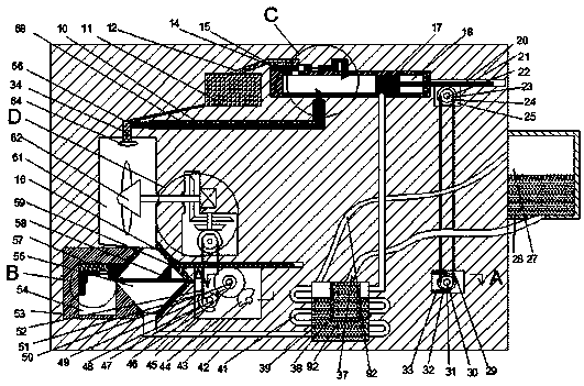
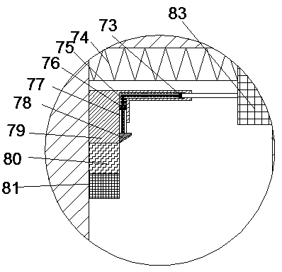
[0021] Combine below Figure 1-5 The present invention will be described in detail. For the convenience of description, the orientations mentioned below are now specified as follows: figure 1 The vertical, horizontal, front and rear directions of the projection relationship are the same.

[0022] A cooling cycle device for machinery of the device of the present invention includes an outer casing 42 in which a turbine cavity 61 is arranged, and a gear cavity 60 is arranged on the right side of the turbine cavity 61, and the gear cavity 60 is There is a transmission assembly, a lubricating oil filter cavity 56 is provided below the turbine cavity 61, a waste storage box 53 is provided on the left side of the lubricating oil filter cavity 56, and a waste storage cavity 54 is provided in the wast...


PUM


Abstract

The invention discloses a cooling circulation device for machinery. The cooling circulation device comprises an outer shell body, wherein a turbine cavity is formed in the outer shell body, a gear cavity is formed in the right side of the turbine cavity, a transmission assembly is arranged in the gear cavity, a lubricating oil filtering cavity is formed below the turbine cavity, a waste storage box is arranged on the left side of the lubricating oil filtering cavity, a waste storage cavity is formed in the waste storage box, a waste assembly is arranged in the waste storage cavity, a transmission cavity is formed in the right side of the lubricating oil filtering cavity, a belt pulley cavity is formed in the rear side of the transmission cavity, and a rotating assembly is arranged in the transmission cavity. Lubricating oil of the device is filtered, then heat is absorbed by a coolant in a cooling box, and then the lubricating oil is circularly used; due to the fact that the boiling point of the coolant for absorbing the heat is low, the coolant for absorbing the heat becomes steam and enters a liquefaction box located at the outside through a pipeline to be cooled and liquefied into the cooling box again, so that the effect of circularly cooling and lubrication is achieved; and meanwhile, the device adopts spray-type lubrication, so that the contact area of the device is wider, and the effect of the device is better.

Description

Technical field [0001] The present invention relates to the field of cooling technology, in particular to a cooling cycle device for machinery. Background technique [0002] my country is a country with high-speed development of mechanical engineering, and the development of machinery is inseparable from high-speed rotating parts such as gears. Parts rotating at high speed will generate a lot of heat. If the heat is not taken away, overheating for a long time will affect the device. Even crashing, while lubricating high-speed rotating parts is not important, and most of the cooling devices now use water to take away heat, the effect is poor, and will waste a lot of water resources. [0003] This device uses lubricating oil that has been used for cooling. It takes away the heat of the parts while lubricating, and then filters and cools it to make it recyclable. The coolant takes the heat from the inside of the device to the outside through the outside temperature difference to reduce...

Claims


Application Information

Patent Timeline
Patent Type & Authority Applications(China)
IPC IPC(8): F01D25/12F01D25/18F16N39/06
CPCF01D25/12F01D25/18F16N39/06F16N2210/02
Inventor 不公告发明人
Owner 徐州法若成制造有限公司
Why Eureka
Try Eureka