
Diaphragm compressor oil path system and cleaning method of oil path system

A diaphragm compressor, oil circuit system technology, applied in mechanical equipment, machinery/engine, liquid variable capacity machinery, etc., to achieve the effect of good lubricating effect

Pending Publication Date: 2020-05-08
SICHUAN JINXING CLEAN ENERGY EQUIP CO LTD +2
View PDF0 Cites 4 Cited by
  • Summary
  • Abstract
  • Description
  • Claims
  • Application Information

AI Technical Summary

Problems solved by technology

[0005] The purpose of the present invention is to: propose a diaphragm compressor oil circuit system and a cleaning method for the oil circuit system, which solves the problem of cleaning the residual substances in the diaphragm compressor oil circuit system

Method used


Image

  • Diaphragm compressor oil path system and cleaning method of oil path system
  • Diaphragm compressor oil path system and cleaning method of oil path system
  • Diaphragm compressor oil path system and cleaning method of oil path system

Examples


Embodiment 1

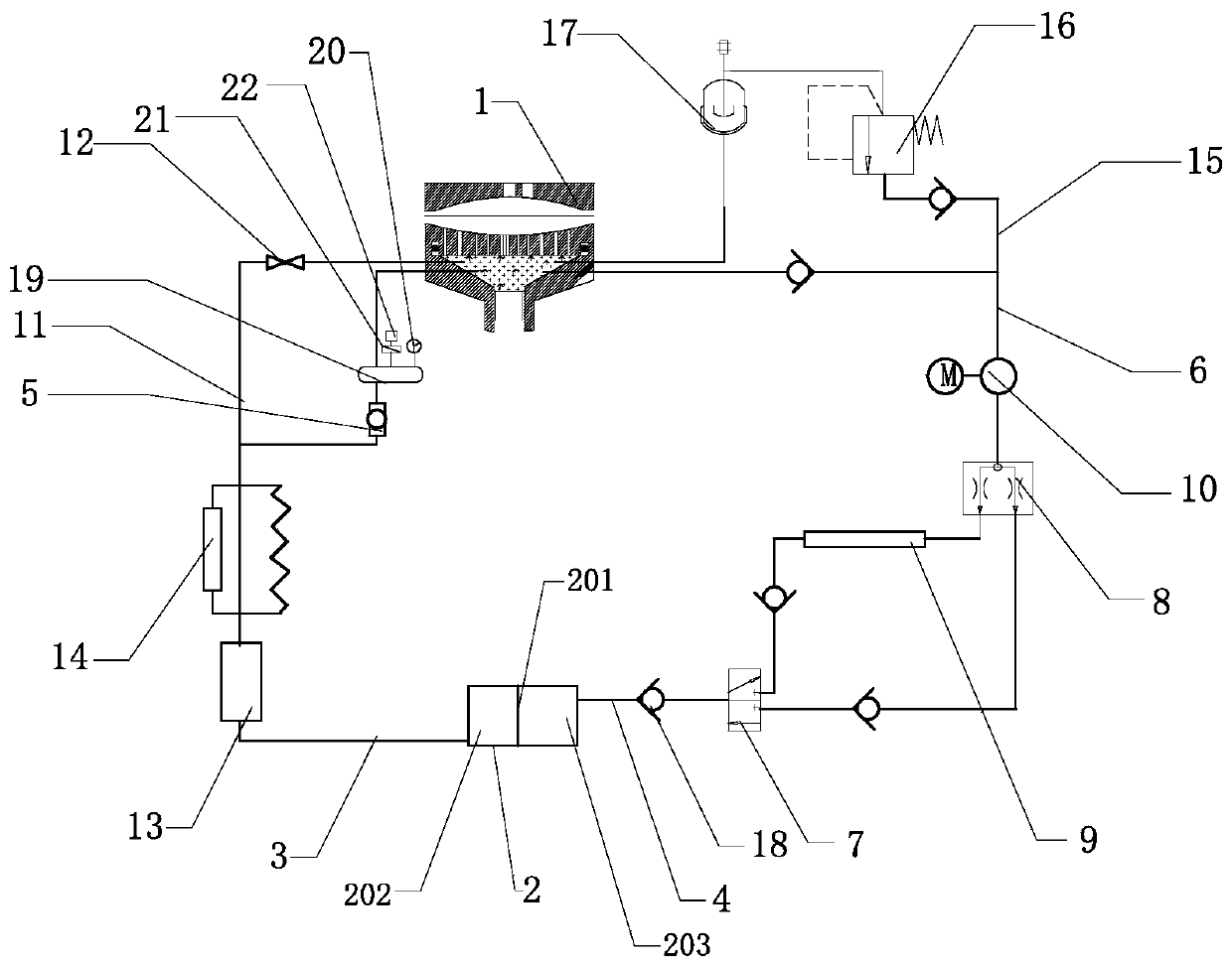
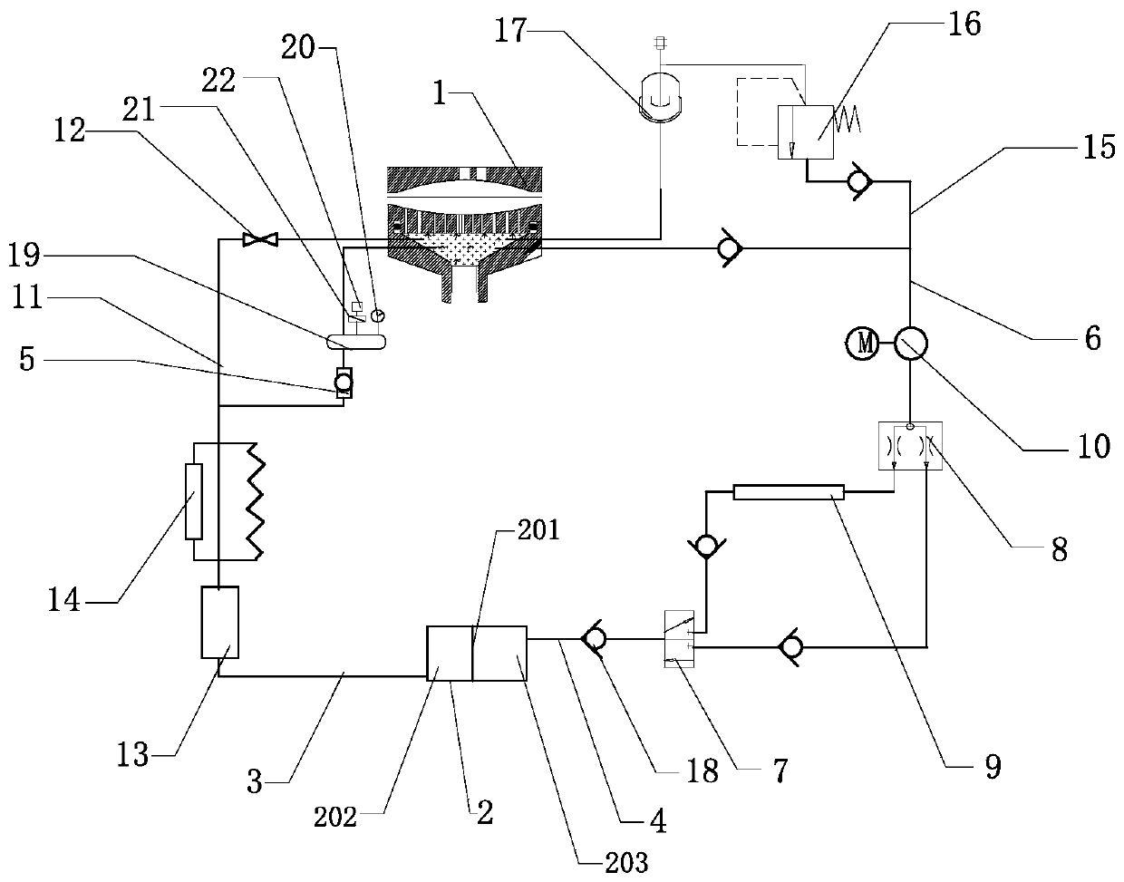
[0041] Such as figure 1 As shown, the present invention is a diaphragm compressor oil circuit system, including an oil cylinder 1 and an oil tank 2, an oil return pipeline 3 and an oil supply pipeline 4 are connected between the oil cylinder 1 and the oil tank 2, and an oil delivery pipeline 6 is also included , the oil pipeline 6 is provided with a temperature control valve 7 and a three-way valve 8 in sequence, the input end of the temperature control valve 7 communicates with the oil tank 2 through the oil supply pipeline 4, and the two outputs of the temperature control valve 7 The ends are respectively communicated with the two input ends of the three-way valve 8 through pipelines, and a cooler 9 is connected to one of the pipelines, and the output end of the three-way valve 8 is connected with an oil pump 10 through a pipeline, and the oil pump 10 It is connected to the oil cylinder 1 through a pipeline and delivers hydraulic oil for the oil cylinder 1; it also includes ...

Embodiment 2

[0045] This embodiment is a further description of the present invention.

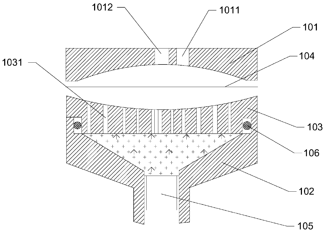
[0046] Such as figure 2 As shown, this embodiment is based on Embodiment 1. In a preferred embodiment of the present invention, the oil cylinder 1 includes a cylinder head 101, a cylinder body 102, an oil distribution plate 103, a diaphragm 104, a piston 105 and a sealing ring 106, the cylinder head 101 is provided with an air intake hole 1011 and an exhaust hole 1012, and the exhaust hole 1012 is arranged at the center of the cylinder head 101, and the oil distribution plate 103 is evenly distributed with oil groove holes 1031, the distribution The oil pan 103 is arranged on the upper end of the cylinder block 102, and a sealing ring 106 is arranged between the two. A curved surface groove is arranged on the cylinder head 101 and the oil distribution pan 103, and the cylinder head 101 and the oil distribution pan 103 form a cavity to Diaphragm 104 is clamped in the middle to form an air chamber and ...

Embodiment 3

[0048] This embodiment is a further description of the present invention.

[0049] Such as figure 1 As shown, this embodiment is based on Embodiment 1. In a preferred embodiment of the present invention, a decompression pipeline 15 is also included, and a decompression valve 16 and a constant pressure valve 16 are connected to the decompression pipeline 15. One end of the decompression pipeline 15 is connected to the oil pump 10, and the other end is connected to the oil cylinder 1 through the decompression valve 16 and the constant pressure device 17 in sequence. When the pressure in the oil supply pipeline 4 and the oil delivery pipeline 6 is too high, the hydraulic oil can be decompressed through the pressure reducing valve 16 in the decompression pipeline 15, and the hydraulic oil is supplied to the oil cylinder 1 to prevent the pressure of the oil delivery pipeline 6 from being too high Damage to the oil circuit system ensures the good lubrication effect of the diaphragm...


PUM


Abstract

The invention discloses a diaphragm compressor oil path system and a cleaning method of the oil path system. The diaphragm compressor oil path system comprises an oil cylinder and an oil tank, whereinan oil return pipeline and an oil supply pipeline are connected between the oil cylinder and the oil tank, the diaphragm compressor oil path system further comprises an oil conveying pipeline, the oil conveying pipeline is sequentially provided with a temperature control valve and a three-way valve, the input end of the temperature control valve communicates with the oil tank through the oil supply pipeline, the two output ends of the temperature control valve communicate with the two input ends of the three-way valve through pipelines respectively, one pipeline is connected with a cooler, and the output end of the three-way valve communicates with an oil pump through a pipeline; and the diaphragm compressor oil path system further comprises an oil-liquid cleaning pipeline, wherein the oil-liquid cleaning pipeline is connected with a one-way valve and a filling oil filter. According to the diaphragm compressor oil path system, a diaphragm compressor is circularly lubricated, residue substances in the diaphragm compressor are cleaned, internal abrasion is reduced, and the service life is prolonged.

Description

technical field [0001] The invention relates to the field of diaphragm compressors, in particular to an oil circuit system of a diaphragm compressor and a cleaning method for the oil circuit system. Background technique [0002] Diaphragm compressor is a volumetric diaphragm compressor with a special structure, which has the characteristics of large compression ratio, good sealing performance, and the compressed gas is not polluted by lubricating oil and other solid residues. Therefore, it is suitable for compressing high-purity, rare, precious, poisonous, harmful and corrosive gases. In the diaphragm compressor, the piston pushes the working oil in the cylinder oil chamber, and then pushes the diaphragm to reciprocate in the diaphragm chamber to change the working volume of the cylinder, and realizes no leakage with the cooperation of the suction and exhaust valves. Periodic work process. In the hydraulic oil circulation system of the diaphragm compressor, the oil leaked ...

Claims


Application Information

Patent Timeline
Patent Type & Authority Applications(China)
IPC IPC(8): F04B45/047F04B39/02F04B39/06F04B39/12F04B39/16F04B49/10F04B49/22F04B41/02F04B51/00
CPCF04B45/047F04B39/02F04B39/06F04B39/122F04B39/125F04B39/16F04B49/10F04B49/22F04B41/02F04B51/00
Inventor 罗钦予罗斌峰杨世宏王勇陈可月刘彬
Owner SICHUAN JINXING CLEAN ENERGY EQUIP CO LTD
Learn More