
Cold shield structure for low-temperature transportation pipeline

A transmission pipeline, low temperature technology, applied in the direction of heat preservation, pipeline protection, pipeline protection through thermal insulation, etc., can solve the problems of reducing pipeline toughness, low welding seam quality and high welding cost

Inactive Publication Date: 2020-05-08
VACREE TECH
View PDF5 Cites 2 Cited by
  • Summary
  • Abstract
  • Description
  • Claims
  • Application Information

AI Technical Summary

Problems solved by technology

The conventional coupling form is often due to the different materials of the cooling pipe and the compensator. To meet the low temperature sealing requirements, it is necessary to add adapters of different materials (that is, one adapter with two materials). The materials of the cooling pipe and the compensator are respectively corresponding to the transition joints. Welding separately has the disadvantages of difficult welding, poor weld quality and high welding cost
[0004] In addition, the connection between the cooling pipe and the cold shield is realized by welding, which will easily cause the wall thickness of the cooling pipe to be locally thinned, and at the same time, welding stress will be generated at the welding seam of the cooling pipe wall, which will reduce the toughness of the pipe.

Method used


Image

  • Cold shield structure for low-temperature transportation pipeline
  • Cold shield structure for low-temperature transportation pipeline
  • Cold shield structure for low-temperature transportation pipeline

Examples


Embodiment Construction

[0017] The following description serves to disclose the present invention to enable those skilled in the art to carry out the present invention. The preferred embodiments described below are only examples, and those skilled in the art can devise other obvious variations.

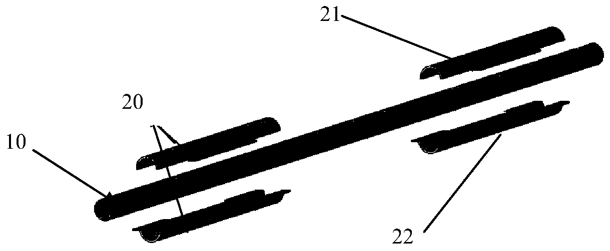
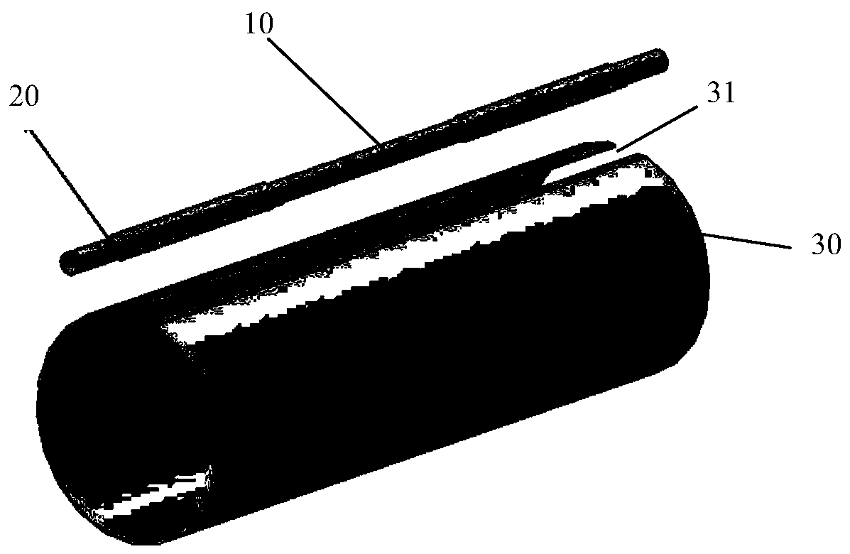
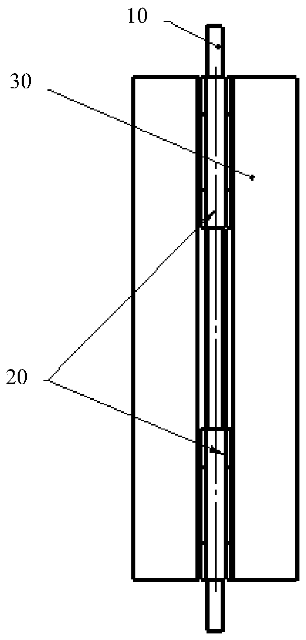
[0018] Such as Figure 1 to Figure 3 As shown, the cold shield structure for the low temperature transmission pipeline includes a cooling pipe 10 , a transition sleeve 20 and a cold shield 30 .

[0019] The outer surface of the cooling pipe 10 is fitted with several transition sleeves 20 along its length. Each transition sleeve 20 is formed by a pair of semi-cylinders (respectively, a first semi-cylinder 21 and a second semi-cylinder 22 ) butted with openings facing each other. The butt connection mode between each pair of half cylinders is the prior art, and there are many specific implementation modes. For example, a buckle structure is provided on the butt straight sides of the half cylinders, and the ...


PUM


Abstract

The invention discloses a cold shield structure for a low-temperature transportation pipeline. The cold shield structure comprises a cold shield and a cooling pipe, and further comprises at least onetransition sleeve which is arranged on the outer surface of the cooling pipe in a sleeving manner, and each transition sleeve is formed through the butt connection of a pair of semicircular cylinderswith opposite openings. Welding plates radially extending outwards are arranged on the outer walls of the transition sleeves; the cold shield is of a cylindrical structure, an axial joint for containing the cooling pipe and the transition sleeves is formed in the cylinder wall of the cold shield, the welding plates are in welding connection with the portions, on the two sides in the circumferential direction of the axial joint, of the cylinder wall in the cold shield, and the cold shield and the transition sleeves are made from a same material. The cold shield structure is easy to weld, high in reliability and wide in application range.

Description

technical field [0001] The invention belongs to the technical field of low-temperature refrigeration, and in particular relates to a cold shield structure for a low-temperature transmission pipeline. Background technique [0002] In order to reduce the heat leakage of cryogenic liquid, especially the large-diameter, long-distance, extremely low-temperature fluid transmission pipeline, a layer is usually added between the extremely low-temperature fluid pipe and the vacuum outer tube, and the temperature is between room temperature and cryogenic fluid. The cold screen structure to reduce the heat leakage of the whole device. The cold shield structure includes a cold shield and a cooling tube. The cold screen is generally a metal material with relatively good thermal conductivity. In order to cool the cold screen, the cooling pipe is usually welded to the cold screen cylinder to realize the transmission of cold energy. [0003] It should be noted that if the connection betwe...

Claims


Application Information

Patent Timeline
IPC IPC(8): F16L59/02
CPCF16L59/024F16L59/028F16L59/029
Inventor 王沛孙志和胡居利黄倩任琪琛丁怀况卢毛磊杜文清滕健
Owner VACREE TECH
Learn More