Reagent needle liquid taking process control method and system of medical instrument

A medical instrument and process control technology, applied in the field of medical devices, can solve problems such as liquid hanging, inaccurate liquid level detection, and long running time of reagent needles, so as to improve accuracy, save running time, and reduce the possibility of liquid hanging at the needle tip sexual effect

Inactive Publication Date: 2020-05-08
SUZHOU HYBIOME BIOMEDICAL ENG CO LTD
View PDF7 Cites 2 Cited by
  • Summary
  • Abstract
  • Description
  • Claims
  • Application Information

AI Technical Summary

Problems solved by technology

[0006] The technical problem to be solved by the present invention is: in order to solve the problems in the prior art that the reagent needle takes too long to run, the liquid hangs, and the detection of the liquid level is inaccurate, thereby providing a method for controlling the liquid extraction process of the reagent needle of the medical instrument and system

Method used


Image

  • Reagent needle liquid taking process control method and system of medical instrument
  • Reagent needle liquid taking process control method and system of medical instrument
  • Reagent needle liquid taking process control method and system of medical instrument

Examples


Embodiment 1

[0063] This embodiment provides a method for controlling the process of taking liquid from a reagent needle of a medical instrument, including:

[0064] 1. Divide the operation process of the reagent needle into multiple stages:

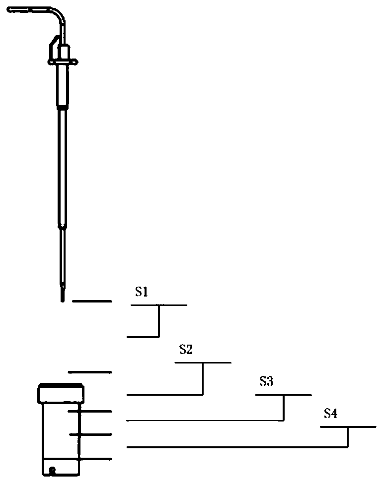
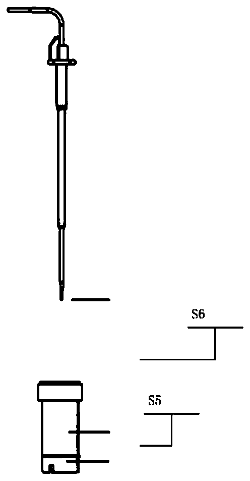
[0065] (1) Divide the process of the reagent needle moving downward from the initial position to the reagent liquid level to draw the reagent into 4 stages, specifically as follows: figure 1 shown, including:

[0066] The first stage S1: the reagent needle moves from the initial position to the set position above the reagent bottle mouth;

[0067] The second stage S2: the reagent needle moves from the set position above the reagent bottle mouth to the set position below the reagent bottle mouth in the reagent bottle;

[0068] The third stage S3: the reagent needle travels from the set position below the mouth of the reagent bottle in the reagent bottle to the first set position above the liquid level in the reagent bottle;

[0069] The fourth stag...

Embodiment 2

[0113] This embodiment provides a reagent needle operation control system for medical instruments, including:

[0114] The operation phase division module is used to divide the liquid extraction process of the reagent needle into multiple operation phases, and set the distance information of each operation phase. For the division of operation phases, refer to Embodiment 1.

[0115] The parameter setting module is used to set operation control parameters, including the operation mode, operation time and operation speed of each operation stage. For the setting of operation control parameters, refer to Embodiment 1.

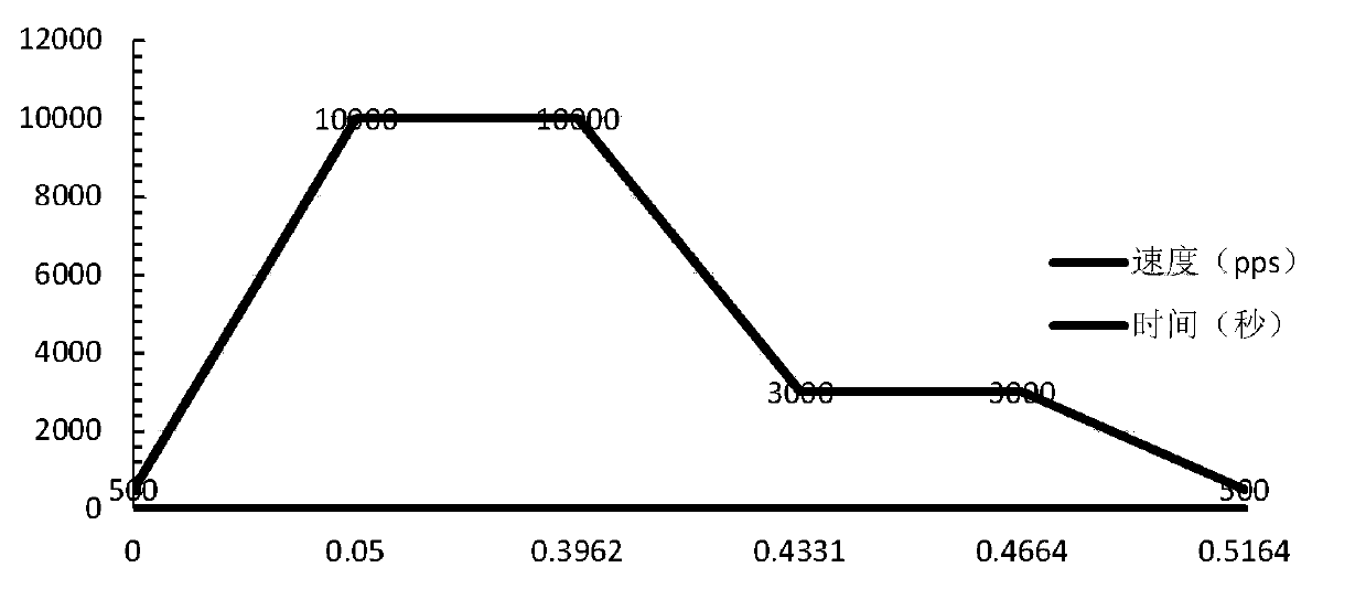
[0116] The operation control module is used to control the reagent needle to complete the operation of each stage according to the set operation control parameters, including: according to the set operation control parameters, control the reagent needle to run from the initial speed according to the set operation control parameters to the nth Operation stage, the ...


PUM


Abstract

The application relates to a reagent needle liquid taking process control method and system for a medical instrument. The method comprises the steps: enabling a reagent needle to operate downwards from an initial position so as to suck a reagent, dividing the reagent sucking process into four stages, and enabling a process that the reagent needle sucks a reagent and then operates upwards to the initial position to be divided into two stages; setting an operation mode and operation time of the reagent needle at each stage; setting the operation mode, the operation time and the operation speed of the reagent needle at each stage; and according to the set operation mode, operation speed and operation time, controlling the reagent needle to finish operation at stages within the preset time. According to the invention, the operation time of the reagent needle is greatly saved, and the problems of overlong operation time, liquid hanging and inaccurate liquid level detection of the reagent needle in the prior art are solved.

Description

technical field [0001] The present application belongs to the technical field of medical devices, and in particular relates to a method and system for controlling a reagent needle extraction process of a medical device. Background technique [0002] At present, in the field of automatic testing of medical devices, reagent needles are generally equipped to transfer reagents from a reagent refrigeration device to a testing device. [0003] The reagent needle is used to absorb and discharge reagents into the sample. In a reagent adding cycle, the reagent needle includes actions such as absorbing reagent, moving horizontally, vertically moving, and discharging reagent. The time spent on each action directly affects the reagent adding cycle. The longer the reagent addition period, the lower the test speed of the automatic analyzer, on the contrary, the shorter the reagent addition period, the higher the test speed of the automatic analyzer. At present, there are problems such as...

Claims


Application Information

Patent Timeline
Patent Type & Authority Applications(China)
IPC IPC(8): G01N35/10
CPCG01N35/10
Inventor 雷瑾瑞
Owner SUZHOU HYBIOME BIOMEDICAL ENG CO LTD
Why Eureka
Try Eureka