Numerical controller

A technology of numerical control device and control unit, applied in the direction of program control, computer control, general control system, etc.

Active Publication Date: 2020-05-08
FANUC LTD
View PDF7 Cites 0 Cited by
  • Summary
  • Abstract
  • Description
  • Claims
  • Application Information

AI Technical Summary

Problems solved by technology

Conversely, these phenomena can be solved by improving the processing ability of the numerical controller to execute pre-reading or execute the machining program, but when the command speed is increased by further miniaturizing the program or improving the machine tool, it still occurs. same question

Method used


Image

  • Numerical controller
  • Numerical controller
  • Numerical controller

Examples


no. 1 approach

[0041] [1.1 Structure of the invention]

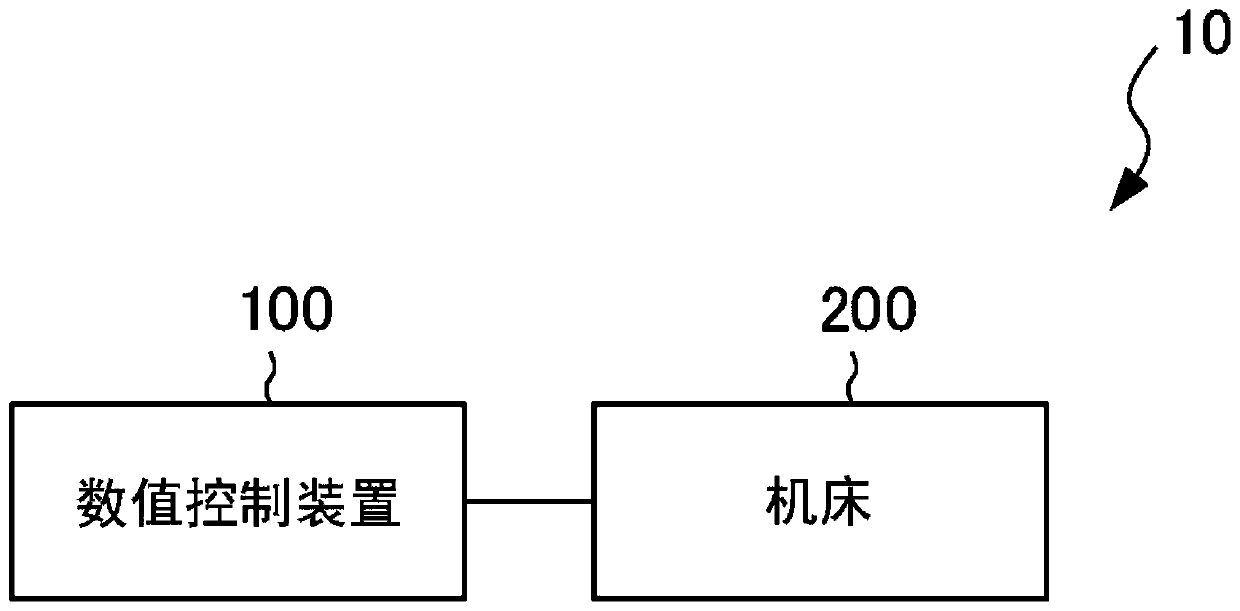
[0042] figure 1 A configuration of a control system 10 including a numerical controller 100 according to the first embodiment of the present invention and a machine tool 200 controlled by the numerical controller 100 is shown.

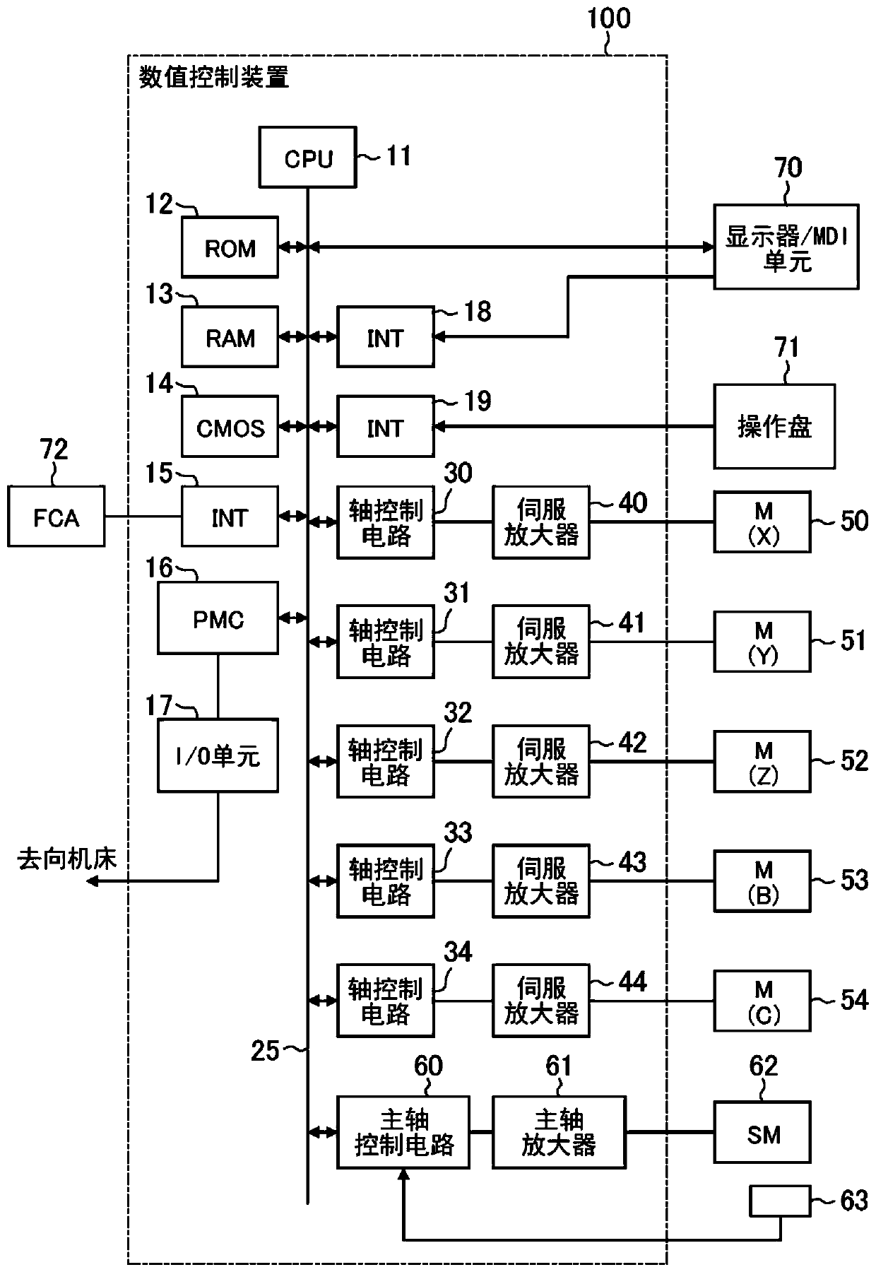
[0043] The numerical control device 100 is a device that outputs operation commands to the machine tool 200 and performs numerical control on the machine tool 200 by having functions described later. Details of the configuration and functions of the numerical controller 100 will be described later.

[0044] The machine tool 200 is an apparatus for performing predetermined machining such as cutting. The machine tool 200 includes a motor driven to machine a workpiece, a main shaft attached to the motor, a feed shaft, jigs, tools, and the like corresponding to these respective shafts. Further, the machine tool 200 performs predetermined machining by driving a motor based on an operation command output from the...

no. 2 approach 〕

[0101] Below, by referring to Figure 9 and Figure 10 A second embodiment of the present invention will be described. In addition, in order to simplify the description, the numerical control device 100A according to the second embodiment will be mainly described below in terms of differences from the numerical control device 100 according to the first embodiment.

[0102] [2.1 Structure of the invention]

[0103] A numerical controller 100A according to the second embodiment is different from the numerical controller 100 according to the first embodiment in that it includes a CPU 11A instead of the CPU 11 .

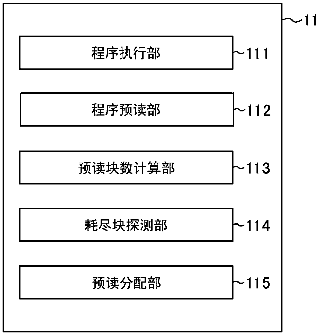
[0104] Figure 9 is a functional block diagram of the CPU 11A. Unlike the CPU 11 , the CPU 11A does not include the look-ahead block number calculation unit 113 and the exhausted block detection unit 114 , but instead includes a machining accuracy index calculation unit 116 and a machining accuracy required block detection unit 117 .

[0105] The machining accuracy ...


PUM


Abstract

To provide a numerical controller that can detect a position in a machining program at which a speed control abnormality is likely to occur due to an insufficient look-ahead blocks that are used to determine an acceleration / deceleration operation, and start a look-ahead processing function from the position in parallel with looking ahead at the machining program from the start of the machining program. The numerical controller (100) includes a program execution unit (111) that executes a machining program, a program look-ahead unit (112) that simultaneously looks ahead at the machining programfrom different blocks in the machining program in parallel with execution of the machining program and that includes a first program look-ahead unit (112a) and a second program look-ahead unit (112b), and a look-ahead allocation unit that divides a storage unit into at least a first region and a second region and instructs the first program look-ahead unit (112a) to perform a look-ahead action ofstoring look-ahead blocks in the first region and instructs the second program look-ahead unit (112b) to perform a look-ahead action of storing look-ahead blocks in the second region.

Description

technical field [0001] The invention relates to a numerical control device. Background technique [0002] In the recent manufacturing industry, the miniaturization and precision of IT parts and the like have been progressing, and interest in high-speed and high-precision machining has been increasing. In order to achieve higher-quality machining, there is an increasing tendency to create machining programs for workpieces under high-speed, high-precision machining with an allowable error (tolerance) of an order of magnitude smaller. [0003] With regard to processing programs with small tolerances that were previously unrealistic from the viewpoint of PC processing capability, due to the improvement of PC performance and CAM (Computer Aided Manufacturing) performance in recent years, it is possible to sufficiently create such processing programs with small tolerances, And it is believed that its momentum will accelerate in the future. [0004] In addition, in addition to to...

Claims


Application Information

Patent Timeline
Patent Type & Authority Applications(China)
IPC IPC(8): G05B19/4155
CPCG05B19/4155G05B2219/33127G05B2219/35386G05B19/408G05B2219/42173
Inventor 上西大辅丹后力
Owner FANUC LTD
Why Eureka
Try Eureka