Numerical controller

a controller and controller technology, applied in the field of numerical controllers, can solve the problems of inability to secure the look-ahead blocks used to determine the acceleration/deceleration operation, the inability to realistically use the machining programs with small tolerances, and the inability to achieve quality machining, etc., to achieve the effect of stabilizing feed rate, cutting speed and other factors, and reducing the likelihood of the required look-ahead blocks being incorr

Active Publication Date: 2020-04-30
FANUC LTD
View PDF0 Cites 0 Cited by
  • Summary
  • Abstract
  • Description
  • Claims
  • Application Information

AI Technical Summary

Benefits of technology

[0123]The numerical controller 100 according to the embodiment of the present invention includes the look-ahead blocks calculation unit 113 that calculates the look-ahead blocks, which is the difference between a first sequence number that is the number of a block in the machining program that is being executed and a second sequence number that is the number of a block that is looked ahead, the required look-ahead blocks setting unit 114 that sets a required look-ahead blocks, which is the look-ahead blocks required for executing the machining program, and the operation limitation unit 116 that compares the look-ahead blocks to the required look-ahead blocks and, if the look-ahead blocks is less than the required look-ahead blocks, limits execution of the machining program until the look-ahead blocks reaches the required look-ahead blocks.
[0124]With this configuration, it is possible to detect the position in the machining program at which a speed control abnormality is likely to occur due to an insufficient look-ahead blocks that are used to determine an acceleration / deceleration operation, and supplement the look-ahead blocks at that position in order to stabilize feed rate, cutting speed and other factors.
[0125]The numerical controller 100 also includes a storage unit that stores blocks to be looked ahead, where the stored blocks are consumed by executing the program. The required look-ahead blocks setting unit 114 sets the required look-ahead blocks on the basis of the maximum capacity of the storage unit.
[0126]As a result, the required look-ahead blocks can be set according to the capacity of the storage unit (for example, a buffer) that stores the look-ahead blocks, and the likelihood of the required look-ahead blocks being incorrect can be reduced.
[0127]The numerical controller 100 also includes a memory that stores the required look-ahead blocks, and the required look-ahead blocks setting unit 114 uses the required look-ahead blocks stored in the memory to set the required look-ahead blocks.
[0128]As a result, if, for example, a required look-ahead blocks needs to be set for each of a plurality of machining programs, management of the required look-ahead blocks can be made simple.

Problems solved by technology

Conventionally, machining programs with small tolerances could not realistically be used due to low computer processing power.
However, such high-quality machining programs have the following problem.
That is, the programs have short minute straight lines and fast command speed which means that, if the processing time for executing the program is shorter than the time required for look-ahead processing, the look-ahead blocks used to determine the acceleration / deceleration operation cannot be secured.
As a result, acceleration / deceleration is not determined in consideration of program behavior and changes in speed are not constant and high-quality machining cannot be achieved.
At 2,000 mm / min, there was insufficient processing time for executing the program and the look-ahead blocks used to determine the acceleration / deceleration operation could not be secured.
However, similar problems occur when command speed is further increased by making programs more detailed or updating machines.
In particular, the technology determines that there is insufficient data when the amount of data predicted to exist in the buffer falls below a lower limit threshold value.

Method used


Image

  • Numerical controller
  • Numerical controller
  • Numerical controller

Examples


modification examples

5. MODIFICATION EXAMPLES

5.1 Modification Example 1

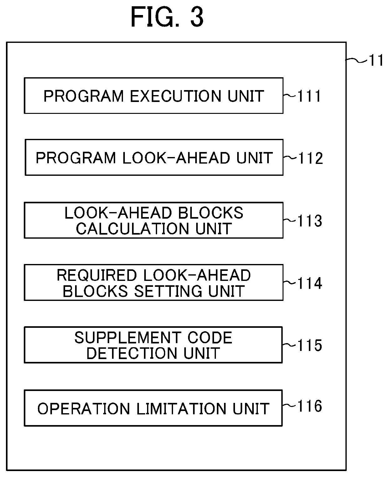
[0137]In the above-described example, the operation limitation unit 116 compares the look-ahead blocks to the required look-ahead blocks to detect a block at which a speed control abnormality is likely to occur, and supplements the look-ahead blocks at that block. However, the operation limitation unit 116 is not limited to this configuration.

[0138]For example, the operation limitation unit 116 may supplement the look-ahead blocks when the rate of reduction of the look-ahead blocks exceeds a prescribed value.

modification example 2

5.2 Modification Example 2

[0139]In the above-described embodiment, the look-ahead block supplement code is inserted into the machining program, but the present invention is not limited to this configuration. For example, the numerical controller 100 may include a “supplement code addition unit” that detects the position of an “exhaustion block” at which the look-ahead blocks falls below a prescribed value when the first simulation is executed, and that automatically inserts the look-ahead block supplement code into the exhaustion block.

[0140](In this embodiment, the “look-ahead block supplement code” that is inserted by the supplement code addition unit is also referred to as a “third code”.)

[0141]An embodiment of the present invention has been described above, but the present invention is not limited to the above-described embodiment.

[0142]Any described effects are merely the best effects achieved by the present invention and the effects achieved by the present invention are not li...


PUM


Abstract

To provide a numerical controller that can detect a position in a machining program at which a speed control abnormality is likely to occur due to an insufficient look-ahead blocks that are used to determine an acceleration/deceleration operation, and supplement the look-ahead blocks at that position in order to stabilize feed rate, cutting speed and other factors. A numerical controller includes a required look-ahead blocks setting unit that sets a required look-ahead blocks, which is a look-ahead blocks required to execute a machining program, and an operation limitation unit that compares a look-ahead blocks calculated by a look-ahead blocks calculation unit to the required look-ahead blocks and, if the look-ahead blocks is less than the required look-ahead blocks, limits execution of the machining program until the look-ahead blocks reach the required look-ahead blocks.

Description

[0001]This application is based on and claims the benefit of priority from Japanese Patent Application No. 2018-205701, filed on 31 Oct. 2018, the content of which is incorporated herein by reference.BACKGROUND OF THE INVENTIONField of the Invention[0002]The present invention relates to a numerical controller.Related Art[0003]In the manufacturing industry today, IT parts and other devices are being manufactured on smaller scales and with higher precision, and interest in high-speed and high-precision machining is on the rise.[0004]In order to achieve even higher quality in machining, there has been an increase in the number of workpiece machining programs for high-speed and high-precision machining that are created with tolerances on smaller orders.[0005]Conventionally, machining programs with small tolerances could not realistically be used due to low computer processing power. However, in recent years, both computer performance and computer aided manufacturing (CAM) performance ha...

Claims


Application Information

Patent Timeline
Patent Type & Authority Applications(United States)
IPC IPC(8): G05B19/4155G05B19/416
CPCG05B2219/43009G05B2219/42173G05B19/4155G05B19/416G05B19/4142G05B2219/34013G05B2219/35293G05B2219/35386
Inventor UENISHI, DAISUKETANGO, CHIKARA
Owner FANUC LTD
Why Eureka
Try Eureka