Chip self-destruction device

A self-destructing device and chip technology, applied in the field of electronic information security, can solve the problems of inconvenient installation, high manufacturing cost, complex structure, etc., and achieve the effects of convenient installation, simple structure and stable performance

Pending Publication Date: 2020-05-08
湖南博远翔电子科技有限公司
View PDF1 Cites 2 Cited by
  • Summary
  • Abstract
  • Description
  • Claims
  • Application Information

AI Technical Summary

Problems solved by technology

Traditional self-destruction methods are mostly limited to software-controlled self-destruction, and the inside of the chip is burned by electricity. However, because the chip is not completely physically damaged, it is possible to obtain fragment information after physical repair, and there are still certain security risks.
[0003] Although there are also some devices on the market that physically destroy electronic chips, some of these devices have complex structures that lead to high manufacturing costs; It needs to be compressed and stored during installation, which is not convenient for installation; some provide independent battery or power supply to work normally, etc.

Method used


Image

  • Chip self-destruction device
  • Chip self-destruction device
  • Chip self-destruction device

Examples


Embodiment 1

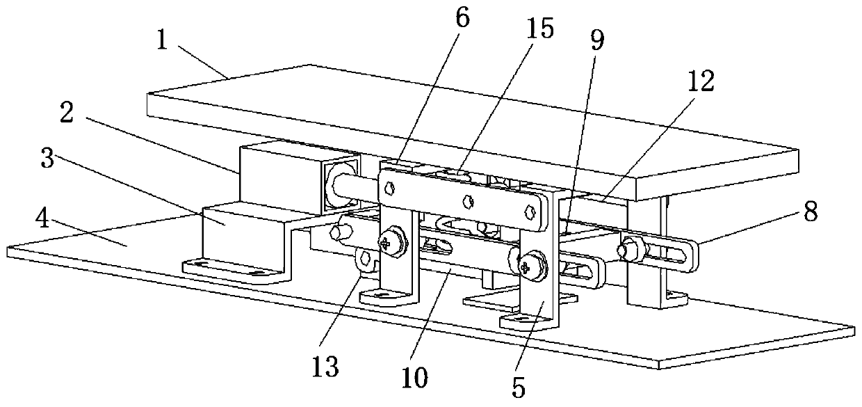
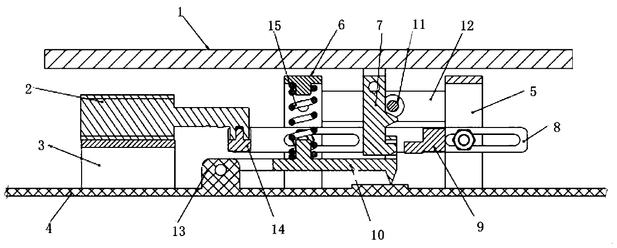
[0034] Reference image 3 with Figure 5 When the electronic product is in use, the administrator inputs special instructions to the control module on the printed board PCB to control the power module to work, so that the input voltage reaches the electromagnetic switch through the power module, and the electromagnetic switch 2 is energized. 2 After power on, the internal structure can generate magnetic force, and the movable rod 14 of the electromagnetic switch 2 is attracted, and the movable rod 14 is moved to the left, so that the sliding link 8 moves to the left, and the push rod 9 moves to the left together with the sliding link 8 , The push rod 9 pushes the movable hook 7 away from the hole of the movable plate 10, and one end of the push rod 9 is clamped into the hole of the movable plate 10 to limit the movement of the movable plate 10, so that the movable plate 10 remains in place for protection effect.

[0035] In this embodiment, the chip self-destruction device is aut...

Embodiment 2

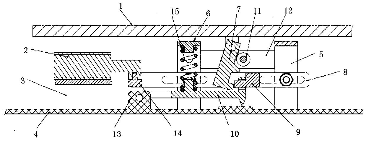
[0037] Reference Figure 4 When the electronic product is powered off, the electromagnetic switch 2 is not magnetic, the hook of the movable hook 7 is located in the hole of the movable plate 10, and one end of the push rod 9 is located outside the hole of the movable plate 10. When the heat dissipation cold plate 1 is removed, the movable hook 7 will be driven to move up, and the movable hook 7 will move up to drive the movable plate 10 to swing upwards. The spring 15 is compressed. When the movable hook 7 moves up a certain distance, the The boss is in contact with the limit rod 11, urging the movable hook 7 to be squeezed away to swing to the side close to the spring 15 until the movable hook 7 is separated from the hole of the movable plate 10, and the spring 15 stretches. Under the force of the spring 15, The movable plate 10 swings downward, and the damage sharp point of the movable plate 10 will cause the damage of the memory chip, so as to achieve the purpose of protecti...


PUM


Abstract

The invention discloses a chip self-destruction device. The invention belongs to the technical field of electronic information security. The device is arranged between a heat dissipation cold plate and a printed board PCB. The device comprises a rotatable movable hook, a rotatable movable plate, a horizontally arranged sliding connecting rod, a spring and a limiting rod which is used for pushing the movable hook; the free end of the movable plate is provided with a clamping hole and a downward destroying sharp point; the hook part of the lower end of the movable hook and one end of the pushingrod of the sliding connecting rod are both matched with the clamping hole of the movable plate; the movable hook and the pushing rod are located at different sides of the movable plate. According tothe chip self-destruction device, when a chip is used, the chip self-destruction device is automatically prohibited, so that accidental self-destruction is prevented, and therefore, the chip is protected. The chip self-destruction device has the advantages of stable performance, convenient installation and simple structure. The device can perform self-destruction protection automatically after thechip is powered off, so that the device is convenient to use.

Description

Technical field [0001] The invention relates to the technical field of electronic information security, in particular to a chip self-destruction device. Background technique [0002] With the rapid development of electronic information technology, the security, anti-theft, and confidentiality of electronic information have become important issues today. Traditional self-destruction methods are mostly limited to software-controlled self-destruction, and the chip is burnt due to over-voltage. However, because the chip is not completely physically damaged, it is possible to obtain fragment information after physical repair. There are still certain security risks. [0003] Although there are some devices on the market that physically destroy electronic chips, some of these devices are complicated in structure and cause high manufacturing costs; some are inconvenient to install. For example, the patent publication number CN108052837A proposes a chip mechanical self-destruction device wi...

Claims


Application Information

Patent Timeline
Patent Type & Authority Applications(China)
IPC IPC(8): G06F21/87G06F21/78
CPCG06F21/78G06F21/87
Inventor 李波谷志军何璐李鼎陈永贵
Owner 湖南博远翔电子科技有限公司
Why Eureka
Try Eureka