3D printing quantitative feeding device, 3D printer and 3D printing method

A 3D printing and feeding device technology, applied in 3D object support structures, ceramic molding machines, additive manufacturing, etc., can solve problems such as poor printing accuracy, achieve the effect of saving materials and improving printing accuracy

Active Publication Date: 2020-05-12
HANS LASER TECH IND GRP CO LTD
View PDF16 Cites 2 Cited by
  • Summary
  • Abstract
  • Description
  • Claims
  • Application Information

AI Technical Summary

Problems solved by technology

[0003] The technical problem to be solved by the present invention is: the 3D printer needs to be used to print relatively viscous materials, which brings about the problem of poor printing accuracy

Method used


Image

  • 3D printing quantitative feeding device, 3D printer and 3D printing method
  • 3D printing quantitative feeding device, 3D printer and 3D printing method
  • 3D printing quantitative feeding device, 3D printer and 3D printing method

Examples


Embodiment 1

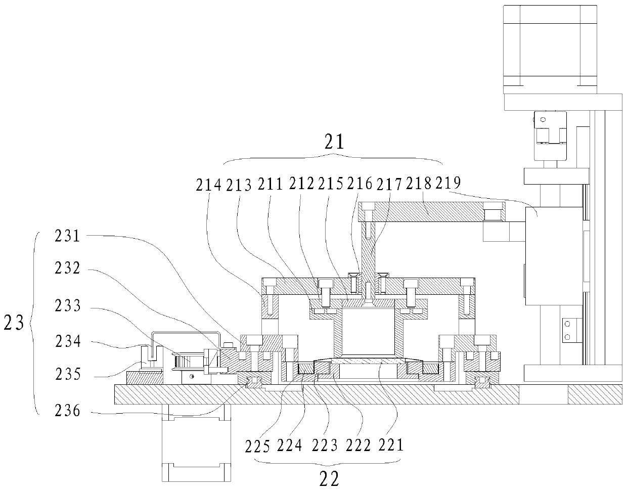
[0031] The feeding assembly includes a material box 211, a guide shaft 217, a pressing rod 218 and an extruding plate 215. The upper part of the guiding shaft 217 is connected to the pressing bar 218, and the lower part of the guiding shaft 217 is connected to the extruding plate 215. The extruding plate 215 cooperates with the inner diameter of the material box 211 , and the bottom of the material box 211 is arranged on a plane.

[0032] Specifically, the material box 211 is used to contain printing materials, the bottom of the material box 211 is parallel to the glass of the material loading platform 22, and the distance is 0.1-0.3mm, and the flatness is required when the bottom of the material box 211 is processed. Use as a scraper. The material loading platform 22 drives the material to move. After passing through the material box 211, the material is scraped flat by the bottom of the material box and evenly spread on the material loading platform, creating conditions for ...

Embodiment 2

[0034] A fixing plate 212 is also included, the fixing plate 212 is located above the material box 211 , and the fixing plate 212 and the material box 211 are positioned through magnetic attraction and / or pin holes.

[0035] Specifically, the fixing plate 212 is used to fix the material box 211. The side of the material box 211 is provided with pin holes, and four circular holes are provided on the top for installing a circular magnetic block. The fixed plate 212 Pin holes are provided on the side, and pins are installed. The material of the fixing plate 212 is iron, and the material box 211 is positioned with the fixing plate by the pins, and is fixed on the fixing plate by the suction force of the magnetic attraction. This facilitates the disassembly and replacement of the material box.

Embodiment 3

[0037] The loading platform 22 includes a loading glass plate 221, a transparent film 225, a glass clamping plate 222, a film clamping plate 223 and a pressing plate 224. The glass clamping plate 222 is provided with a slot, and the loading glass plate 221 is installed In the slot of the glass clamp 222, the transparent film 225 covers the film clamp 223, and the surrounding of the transparent film 225 is pressed tightly in the slot of the film clamp 223 by the pressure plate 224, The glass clamp 222 is connected to the film clamp 223 .

[0038] Specifically, the loading platform 22 is used to carry materials. The loading glass plate 221 is made of a transparent material, which can transmit light from the bottom. The glass clamping plate 222 is empty in the middle and has steps around it. The middle of clamping plate 223 is hollow and has grooves all around. The grooves around the film clamping plate 223 match the dimensions of the pressing plate 224, and the hollow dimensions...


PUM


Abstract

The invention discloses a 3D printing feeding device, a 3D printer and a 3D printing method. The 3D printing feeding device comprises a base, a feeding component, a loading platform and a platform driving component, wherein the feeding component, the loading platform and the platform driving component are fixed above the base; the loading platform is positioned at the lower part of the feeding component; the platform driving component is positioned on one side of the loading platform and the feeding component; one end of the platform driving component is connected with the feeding component and the loading platform separately; and the platform driving component drives the loading platform to feed the material to a working area in a directional manner. A magazine extrudes in a quantitativemanner, the platform moves back and forth, the problem about 3D printing of viscous and difficult-to-flow resin is solved, and the 3D printing feeding device can be particularly applied to ceramic 3Dprinting, and 3D printing manufacturing of a dental wainscot and inlay, can realize quantitative feeding and saves the material; the magazine adopts magnetic attraction and a pin hole for positioningand can be conveniently detached and changed; and application of an optical coupler, an photoelectric separation blade and a linear guide rail is precise in positioning and improves the precision.

Description

technical field [0001] The invention relates to a 3D printer, in particular to a 3D printing quantitative feeding device, a 3D printer and a printing method. Background technique [0002] At present, light-curing 3D printers need to be used to print relatively viscous materials, such as adding a certain proportion of ceramic powder to traditional resin materials. This material is relatively viscous and has poor fluidity, so traditional printing liquid tanks are used for feeding and printing , the material is difficult to self-level, resulting in incomplete printing and poor accuracy, thereby reducing the printing accuracy. Contents of the invention [0003] The technical problem to be solved by the present invention is: the 3D printer needs to be used to print relatively viscous materials, which leads to the problem of poor printing accuracy. [0004] In order to solve the problems of the technologies described above, the technical solution adopted in the present inventio...

Claims


Application Information

Patent Timeline
Patent Type & Authority Applications(China)
IPC IPC(8): B29C64/321B29C64/245B29C64/129B29C64/20B28B1/00B33Y40/00B33Y10/00B33Y30/00
CPCB29C64/321B29C64/245B29C64/129B29C64/20B28B1/001B33Y40/00B33Y10/00B33Y30/00
Inventor 宋战波袁剑刘武齐志宏陈小强祁杨停郭雪威吕启涛高云峰
Owner HANS LASER TECH IND GRP CO LTD
Why Eureka
Try Eureka