Eureka AIR delivers breakthrough ideas for toughest innovation challenges, trusted by R&D personnel around the world.

Foundation reinforcement pressure bearing and drawing resisting composite anchorage structure and anchorage method thereof

A technology of foundation reinforcement and anchoring structure, applied in foundation structure engineering, soil protection, sheet pile wall and other directions, can solve the problems of construction difficulty, high noise, time-consuming and laborious, hidden safety hazards of the original foundation, etc., to improve the speed of construction and Efficiency, simplicity of manufacture and installation, quick and convenient construction

Pending Publication Date: 2020-05-12
广东华科大建筑技术开发有限公司 +1
View PDF0 Cites 0 Cited by
  • Summary
  • Abstract
  • Description
  • Claims
  • Application Information

AI Technical Summary

Problems solved by technology

like image 3 As shown, the composite anchoring structure needs to chisel out a section of deep groove 101 on the pile hole 10 of the original foundation. If the depth of chiseling is not enough, the newly added piles will easily rush out of the original foundation cap during the compression process; while chiseling In addition to being too deep, the effect of drawing will be greatly reduced
In addition, mechanical chiseling is required during excavation, which has a great impact on the structural performance of the original foundation, construction difficulty and noise, and a large amount of concrete waste will be generated. In addition, due to the high strength and hard material of concrete in general projects, it takes a long time to excavate , time-consuming and labor-intensive, and it is easy to cause cracks in the original foundation, which brings safety hazards to the original foundation

Method used


Image

  • Foundation reinforcement pressure bearing and drawing resisting composite anchorage structure and anchorage method thereof
  • Foundation reinforcement pressure bearing and drawing resisting composite anchorage structure and anchorage method thereof
  • Foundation reinforcement pressure bearing and drawing resisting composite anchorage structure and anchorage method thereof

Examples


Embodiment

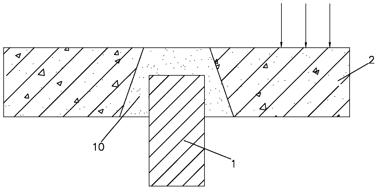
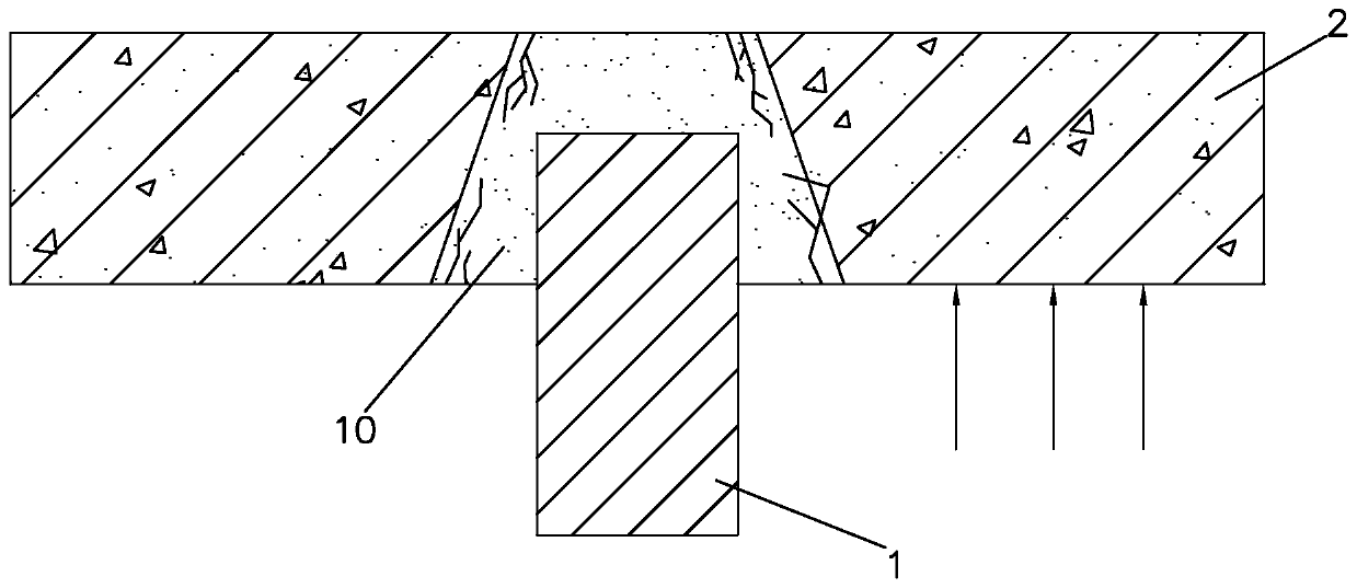
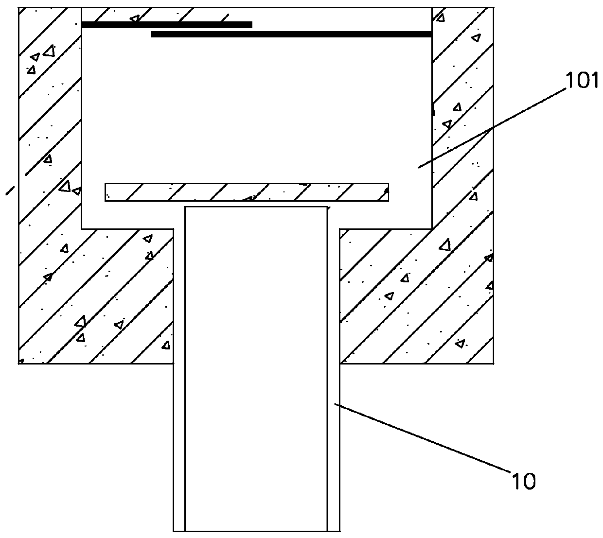
[0033] refer to Figure 4 and Figure 5 , the present embodiment relates to foundation reinforcement compression and pullout composite anchoring structure, including pile top member 1, anchor rod 2, pullout anchor rod 3 and anchor head 4, the pile top member 1 is arranged on the original foundation 10 and the new On the upper surface of the added pile 11, several through holes are opened on the pile top member 1, and the lower ends of the anchor rod 2 and the pullout anchor rod 3 are respectively anchored with the original foundation 10 and the newly added pile 11, and the anchor rod 2 and the The upper end of the uplift anchor rod 3 passes through and extends out of the through hole; the anchor head 4 is arranged on the upper surface of the pile top member 1 , and the anchor head 4 is anchored with the upper ends of the anchor rod 2 and the uplift anchor rod 3 .

[0034] When the newly added pile 11 is subjected to the vertical load from the superstructure, the pile foundati...


PUM


Abstract

The invention discloses a foundation reinforcement pressure bearing and drawing resisting composite anchorage structure. The structure comprises pile top parts, an anchorage pull rod, an anti-pull anchor rod and anchor heads, the pile top parts are mounted on the upper surfaces of an original foundation and a newly-added pile, multiple through holes are formed in the pile top parts, the lower endsof the anchorage pull rod and the anti-pull anchor rod are anchored with the original foundation and the newly-added pile, the upper ends of the anchorage pull rod and the anti-pull anchor rod penetrate through and extend out of the through holes, the anchor heads are mounted on the upper surfaces of the pile top parts, and the anchor heads are anchored with the upper ends of the anchorage pull rod and the anti-pull anchor rod. The invention further discloses an anchorage method. The newly-added pile achieves the vertical bearing function, and achieves the anti-pull effect, a certain depth does not need to be chiseled from a pile hole, a large-power machine is not needed, a large amount of noise cannot be generated, and concrete waste cannot be generated. In addition, the structure does not need a large amount of water for prefabricating concrete, site machining is not needed, manufacturing and mounting are easy, construction is rapid and convenient, and the construction speed and efficiency can be greatly improved.

Description

technical field [0001] The invention belongs to the technical field of buildings, in particular to a composite anchoring structure for foundation reinforcement with pressure bearing and pullout resistance and an anchoring method thereof. Background technique [0002] In foundation reinforcement, various additional pile reinforcement methods are often used, such as: static pressure pile reinforcement method, new steel pipe column reinforcement method, tree root pile reinforcement method, etc. The post-seal pile technology is mainly adopted, that is, the pile hole is reserved in the cap platform first, usually the pile hole is a vertebral body, narrow at the top and wide at the bottom, and then the pile construction is carried out, the pile top extends into the reserved pile hole, and then the existing pile hole is used Pour concrete to seal the reserved pile holes. [0003] The newly added pile 1 will be subjected to two kinds of pulling effects under different working condi...

Claims


Application Information

Patent Timeline
IPC IPC(8): E02D3/08E02D27/12E02D5/74
CPCE02D3/08E02D27/12E02D5/74
Inventor 梁冬王烨璐余冬华陈向红刘锋曾岚梁镇渝黄罗华
Owner 广东华科大建筑技术开发有限公司
Why Eureka
Eureka Blog
Learn More