Pipeline composite dredging dust removal device and dredging dust removal method using same

A technology for dust removal devices and pipes, applied in water supply devices, cleaning sewer pipes, waterway systems, etc., can solve the problems of easy blocking, slow travel, collision, etc., to avoid overload work, remove silt and dust, and improve The effect of work efficiency

Active Publication Date: 2020-05-12
JIANGSU XINGXIN SEPARATION EQUIP MFR
View PDF13 Cites 8 Cited by
  • Summary
  • Abstract
  • Description
  • Claims
  • Application Information

AI Technical Summary

Problems solved by technology

[0005] First of all, the drilling radius of the front rotary drilling structure cannot completely match the inner diameter of the pipe. If the drilling radius is equal to the inner radius of the pipe, it is difficult to coincide with the centerline of the pipe during the drilling process. The drilling bit or blade will collide with the inside of the pipeline, damaging the drilling structure of the pipeline and the dredging device; if the drilling radius is smaller than the inner radius of the pipeline, the sediment attached to the inner wall of the pipeline will not be removed, and the dredging will not be complete;
[0006] Secondly, when the rotary drilling is used for dredging, it is easy to get stuck when encountering large pieces of silt, and the rotary structure is overloaded;
[0007] In addition, if a separate step-by-step walking structure is adopted, the traveling speed is slow when dredging is not performed; when a separate wheel drive structure is adopted, sufficient propulsion cannot be provided during dredging

Method used


Image

  • Pipeline composite dredging dust removal device and dredging dust removal method using same
  • Pipeline composite dredging dust removal device and dredging dust removal method using same
  • Pipeline composite dredging dust removal device and dredging dust removal method using same

Examples


Embodiment Construction

[0038] Next, the inventive concept of the present invention will be described in detail with reference to the accompanying drawings. What is described here is only a preferred embodiment of the present invention, and those skilled in the art can think of other ways to realize the present invention on the basis of the preferred embodiments, and the other ways also fall within the scope of the present invention. In the following detailed description, directional terms such as "upper", "lower", "inner", "outer" and the like are used with reference to the directions described in the accompanying drawings. Components of embodiments of the present invention may be positioned in a variety of different orientations, and directional terms are used for purposes of illustration and not limitation.

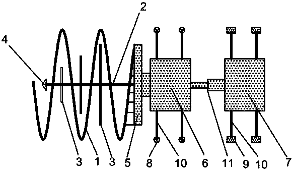
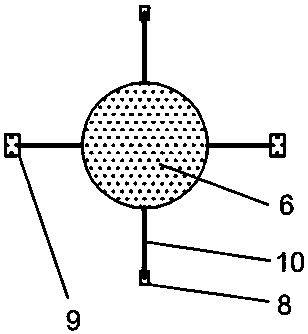
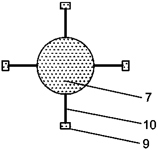
[0039]Referring to the figure, the pipeline compound dredging and dust removal device includes a drilling part and a supporting walking part. The drilling part includes a helical drill rod, a...


PUM


Abstract

The invention relates to a pipeline composite dredging dust removal device and a dredging dust removal method using the same. The pipeline composite dredging dust removal device comprises a drilling part and a supporting walking part, wherein the drilling part comprises a spiral drill rod, a middle drill rod, stirring blades and a conical drill bit, and the supporting walking part comprises a front end supporting seat, a rear end supporting seat, a walking oil cylinder and walking wheels. The spiral drill rod is adopted and combined with the multiple groups of progressive stirring blades on the middle drill rod, so that the whole dredging work can be carried out, deposits and dust of the inner wall of a pipeline can be effectively removed, grading stirring can be carried out, and the overload work can be avoided; and a progressive structure is used and combined with the walking wheels by a walking device, and when the dredging operation is not carried out, the walking device advances quickly by the walking wheels, and when the dredging operation is carried out, the walking device advances by the progressive structure, and the walking wheels are controlled to participate in work according to the pressure of the walking oil cylinder, so that the working efficiency can be improved, and enough travel pushing force can be provided.

Description

technical field [0001] The invention relates to a pipeline dredging and dust removal device, in particular to a pipeline composite dredging and dust removal device and a dredging and dust removal method thereof. Background technique [0002] Municipal drainage pipes refer to rainwater and sewage pipes under municipal roads, commonly known as "sewer pipes", and are usually called municipal drainage pipes in engineering. According to the current situation of the facilities under the municipal roads in China, different pipelines are generally set up, such as electricity, communication, gas, water supply, drainage pipelines and so on. As for the drainage pipes, due to the consideration of rain and sewage diversion measures, that is, the rainwater is generally discharged into the river nearby, and the sewage is discharged into the sewage treatment plant, so the municipal drainage pipes include two kinds of pipes, rainwater and sewage. [0003] Due to the construction and develop...

Claims


Application Information

Patent Timeline
Patent Type & Authority Applications(China)
IPC IPC(8): E03F7/10E03F9/00
CPCE03F7/10E03F9/00E03F9/007E03F7/106
Inventor 揭维敏
Owner JIANGSU XINGXIN SEPARATION EQUIP MFR
Why Eureka
Try Eureka