Engine and engine oil cooling device

An oil cooling and engine technology, applied in the direction of engine cooling, engine components, machines/engines, etc., can solve the problems of large occupied space and acceleration, and achieve the effect of reducing the occupied area, speeding up the cooling speed, and increasing the degree of cooling

Inactive Publication Date: 2020-05-12
广州扬坪机电科技有限公司
View PDF4 Cites 0 Cited by
  • Summary
  • Abstract
  • Description
  • Claims
  • Application Information

AI Technical Summary

Problems solved by technology

[0002] The function of the automobile engine cooling system is to dissipate part of the heat absorbed by the heated parts in time to ensure that the engine works at the most suitable temperature state. The oil cooler is a device that accelerates the heat dissipation of lubricating oil to keep the temperature low For enhanced performance and high-power engines, due to the large heat load, an oil cooler must be installed. Both cooling devices are necessary for the engine. Most cooling systems now separate the two devices, occupying a large area

Method used


Image

  • Engine and engine oil cooling device
  • Engine and engine oil cooling device
  • Engine and engine oil cooling device

Examples


Embodiment Construction

[0013] All features disclosed in this specification, or all disclosed steps in a method or process, may be combined in any way except mutually exclusive features and / or steps.

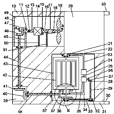
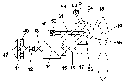
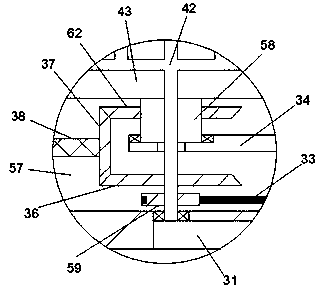
[0014] Combine below Figure 1-3 The present invention is described in detail, for the convenience of description, the orientations mentioned below are now specified as follows: figure 1 The projection relationship of itself is the same as the up, down, left, right, front, and rear directions.

[0015] An engine and oil cooling device of the device of the present invention includes a main body 10, an engine 20 is arranged in the main body 10, an oil inlet 63 is arranged at the upper end of the engine 20, and a cooling cavity 49 is arranged at the left end of the engine 20, A first fixing rod 50 and a second fixing rod 51 are fixedly installed on the lower end wall of the cooling cavity 49 . The upper end of the first fixing rod 50 is hinged with a first connecting rod 61 through a first fixing point 5...


PUM


Abstract

The invention discloses and relates to the field of engine cooling, and particularly relates to an engine and engine oil cooling device. The engine and engine oil cooling device comprises a body, andan engine is arranged in the body. An oil inlet is formed in the upper end of the engine, and a cooling cavity is formed in the left end of the engine. A first fixed rod and a second fixed rod are fixedly mounted on the lower end wall of the cooling cavity, and a first connecting rod is hinged to the upper end of the first fixed rod through a first fixed point. A connecting block is fixedly mounted at the front end of the first connecting rod, and a first driving shaft is rotationally mounted in the connecting block. A motor in power connection with the first driving shaft is arranged at the left end of the first driving shaft, and a worm is fixedly mounted on the first driving shaft. A first rotary shaft is hinged to the other end of the first connecting rod, and a worm wheel engaged withthe worm is fixedly mounted at the lower end of the first rotary shaft. An engine cooling assembly and an engine oil cooling assembly of the device are controlled by the same motor, engine cooling isachieved through air cooling, and engine oil cooling is achieved through water cooling.

Description

technical field [0001] The invention relates to the technical field of engine cooling, in particular to an engine and oil cooling device. Background technique [0002] The function of the automobile engine cooling system is to dissipate part of the heat absorbed by the heated parts in time to ensure that the engine works at the most suitable temperature. The oil cooler is a device that accelerates the heat dissipation of lubricating oil and keeps the temperature lower. On the enhanced engine with high performance and high power, due to the large heat load, an oil cooler must be installed. Both cooling devices are necessary for the engine. Most cooling systems now separate the two devices and occupy a large area. . SUMMARY OF THE INVENTION [0003] In view of the deficiencies of the above technologies, the present invention proposes an engine and oil cooling device, which can overcome the above deficiencies. [0004] An engine and oil cooling device of the present inventi...

Claims


Application Information

Patent Timeline
Patent Type & Authority Applications(China)
IPC IPC(8): F01P5/04F01P11/08F01M5/00F01M11/02
CPCF01M5/002F01M11/02F01P5/04F01P11/08F01P2005/046
Inventor 不公告发明人
Owner 广州扬坪机电科技有限公司
Why Eureka
Try Eureka