[0026] In order to make the technical means, creative features, goals and effects achieved by the present invention easy to understand, the present invention will be further described below in conjunction with specific embodiments.
[0027] In the description of the present invention, it should be noted that the terms "upper", "lower", "inner", "outer", "front end", "rear end", "both ends", "one end", "another end" The orientation or positional relationship indicated by etc. is based on the orientation or positional relationship shown in the drawings, and is only for the convenience of describing the present invention and simplifying the description, rather than indicating or implying that the referred device or element must have a specific orientation, use a specific Azimuth configuration and operation, therefore, should not be construed as limiting the invention. In addition, the terms "first" and "second" are used for descriptive purposes only, and should not be understood as indicating or implying relative importance.
[0028] In the description of the present invention, it should be noted that, unless otherwise specified and limited, the terms "installed", "set with", "connected", etc. should be understood in a broad sense, such as "connected", which may be a fixed connection , can also be detachably connected, or integrally connected; can be mechanically connected, can also be electrically connected; can be directly connected, can also be indirectly connected through an intermediary, and can be internal communication between two components. Those of ordinary skill in the art can understand the specific meanings of the above terms in the present invention in specific situations.
[0029] The following will clearly and completely describe the technical solutions in the embodiments of the present invention with reference to the accompanying drawings in the embodiments of the present invention. Obviously, the described embodiments are only some, not all, embodiments of the present invention. Based on the embodiments of the present invention, all other embodiments obtained by persons of ordinary skill in the art without making creative efforts belong to the protection scope of the present invention.
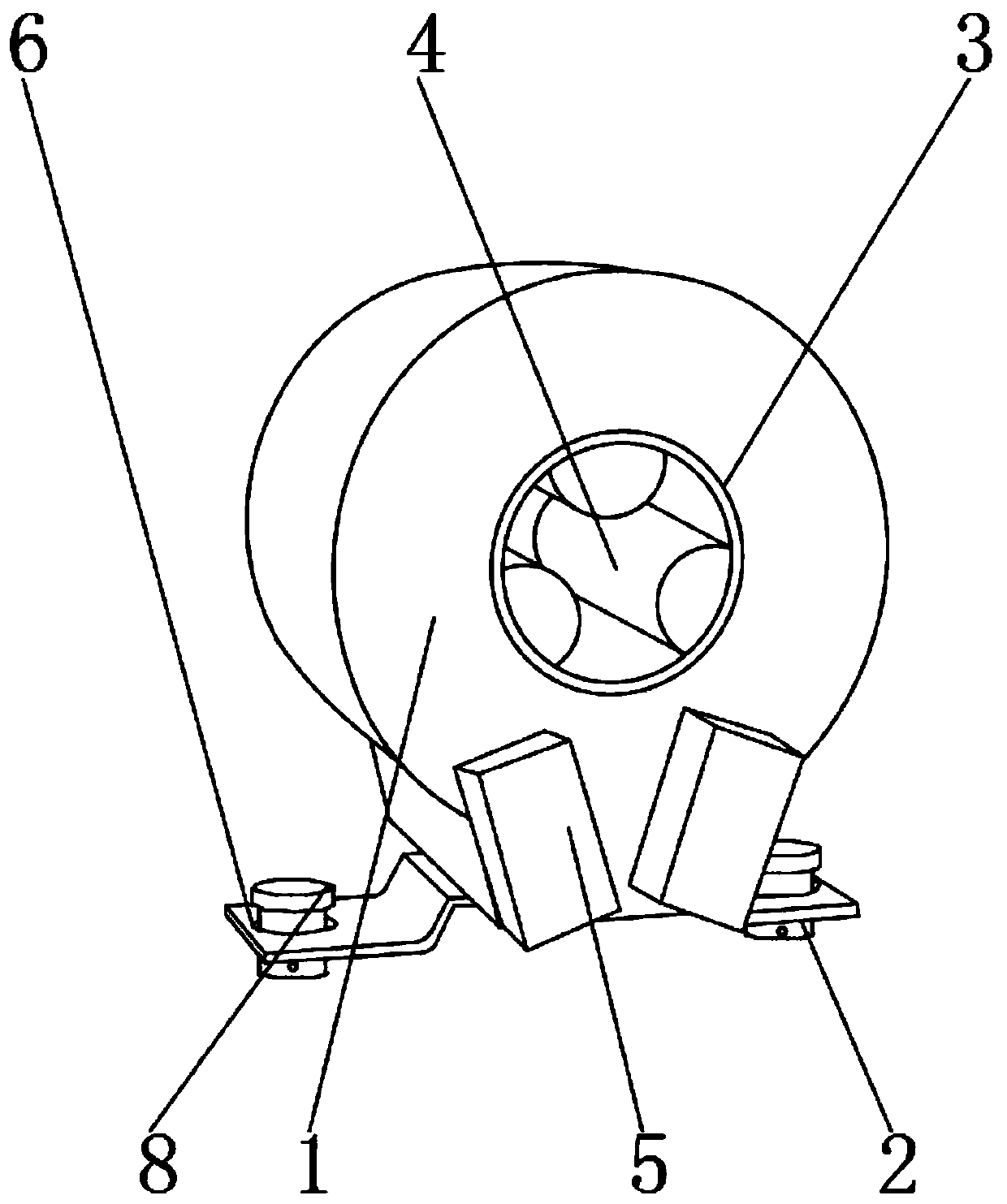
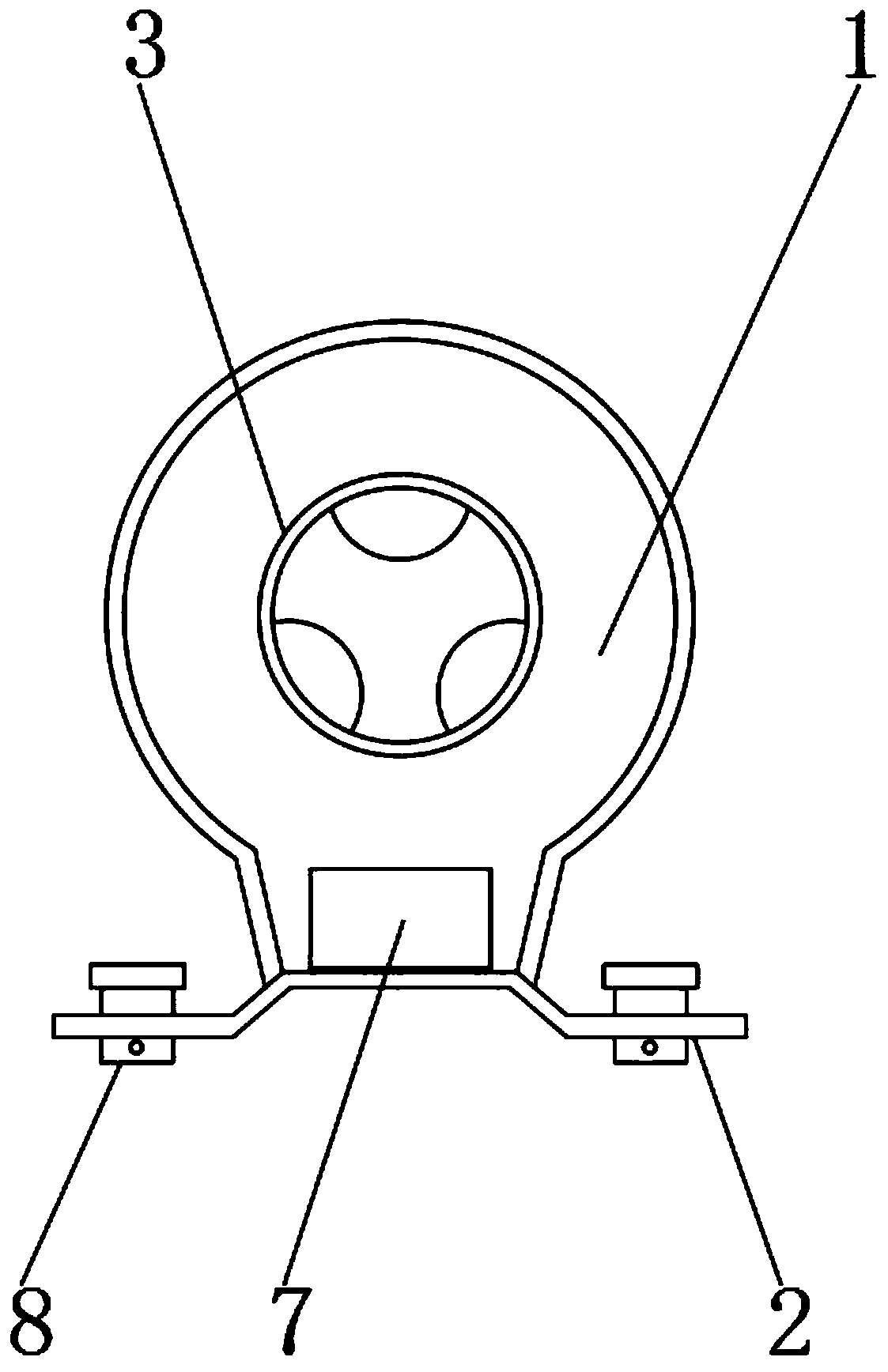
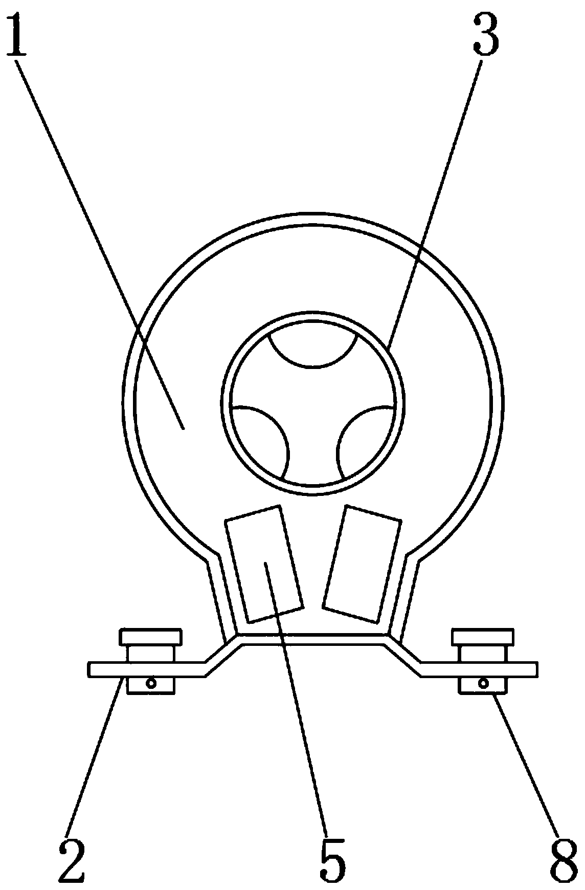
[0030] see Figure 1-6 , the present invention provides a technical solution: a feed-through current transformer, including a feed-through current transformer main body 1, the outer surface of the front end of the feed-through current transformer main body 1 is provided with a sealing mechanism I5, and the feed-through current transformer The outer surface of the rear end of the current transformer main body 1 is provided with a sealing mechanism II7, and the outer surface of the lower end of the through-hole current transformer main body 1 is provided with a fixed mounting frame 2, and a fixing hole 6 is opened inside the fixed mounting frame 2, and the fixing hole The interior of 6 is provided with fixing mechanism 8.
[0031] It can seal and protect the joints of the device. In this embodiment, preferably, the sealing mechanism I5 includes an insulating sealing shell 501, a U-shaped fixing groove 502, a U-shaped sealing ring 503 and a permanent magnet piece 504, and the U-shaped fixing groove 502 is set On the outer surfaces of both ends of the insulating sealing shell 501 , the U-shaped sealing ring 503 is located inside the U-shaped fixing groove 502 , and the permanent magnet sheet 504 is located on the inner wall around the insulating sealing shell 501 .
[0032] It can improve the flame retardancy and moisture resistance of the joint. In this embodiment, preferably, a hot melt adhesive is provided between the U-shaped fixing groove 502 and the U-shaped sealing ring 503, and one side of the U-shaped sealing ring 503 The hot melt adhesive is fixedly connected to the inner surface of the U-shaped fixing groove 502, and an installation groove is provided between the permanent magnet sheet 504 and the insulating sealing shell 501, and one side of the outer surface of the permanent magnet sheet 504 is sealed with the insulation through the installation groove. The inner wall of the shell 501 is fixedly connected.
[0033] It is convenient for people to fix and install the device. In this embodiment, preferably, the fixing mechanism 8 includes a fixing bolt post 801, a fixing nut 802, a contraction groove 803, a return spring 804 and a movable steel ball 805, and the fixing nut 802 is located on the fixing nut. At one end of 802 , the contraction groove 803 is opened inside the fixed bolt 801 , and the movable steel ball 805 and the return spring 804 are located inside the contraction groove 803 .
[0034] It is convenient for the staff to install and disassemble the device. In this embodiment, preferably, the outer wall of the movable steel ball 805 is movably connected with the outer surface of one end of the contraction groove 803 through the return spring 804. The number of the fixing mechanisms 8 is two groups, and the contraction groove The quantity of 803, back-moving spring 804 and movable steel ball 805 is four groups.
[0035] The stability between the cable and the main body 1 of the feedthrough current transformer can be improved. In this embodiment, preferably, the inside of the main body 1 of the feedthrough current transformer is provided with a cable through hole 3, and the inside of the cable through hole 3 is fixedly connected There are rubber fixing rings 4, the number of rubber fixing rings 4 is three groups, and the number of sealing mechanism I5 is two groups.
[0036]The stability when the device is fixed can be improved. In this embodiment, preferably, a fixing screw is provided between the main body 1 of the through-hole current transformer and the fixed mounting frame 2, and the outer surface of the upper end of the fixed mounting frame 2 is connected to the fixed screw by the fixing screw. The outer surface of the lower end of the main body 1 of the through-type current transformer is fixedly connected, and the number of fixing screws is two groups.
[0037] It is convenient for people to install and disassemble the sealing mechanism I5. In this embodiment, preferably, the outer surface of one side of the sealing mechanism I5 is fixedly connected with the outer surface of one side of the main body 1 of the through-hole current transformer through the permanent magnetic sheet 504. The outer surfaces of the sealing mechanism I5, the sealing mechanism II7 and the main body 1 of the feed-through current transformer are all provided with a fireproof coating.
[0038] working principle
[0039] The patent application for this invention consists of the main body 1 of the core-through current transformer, the fixed mounting frame 2, the cable perforation 3, the rubber fixed ring 4, the sealing mechanism I5, the insulating sealing shell 501, the U-shaped fixing groove 502, the U-shaped sealing ring 503, and the permanent The magnetic sheet 504, the fixing hole 6, the sealing mechanism II7, the fixing mechanism 8, the fixing bolt column 801, the fixing nut 802, the contraction groove 803, the return spring 804 and the movable steel ball 805 are composed of components. The main body 1 of the device is fixed at the designated position through the cooperation of the fixed installation frame 2 and the fixing mechanism 8, so that people can use it normally. Quick installation and disassembly work, the disassembly and installation steps can be completed without the cooperation of tools, and it is convenient for the staff to repair and maintain the main body 1 of the feed-through current transformer in the later stage. After the main body 1 of the feed-through current transformer is fixed, the The cable passes through the rubber fixing ring 4 and the cable through hole 3 through the inside of the feed-through current transformer main body 1. At this time, the rubber fixing ring 4 can improve the fastness between the cable and the feed-through current transformer main body 1, Next, connect the required transmission line to the main body 1 of the feed-through current transformer. After the connection, seal the joint through the sealing mechanism I5 and the sealing mechanism II7, and the U-shaped fixing groove 502 and the U-shaped sealing ring 503 can improve the sealing. performance, avoiding moisture absorption, and can effectively increase the flame retardant effect, further ensuring the service life of the main body 1 of the feedthrough current transformer.
[0040] The basic principles and main features of the present invention and the advantages of the present invention have been shown and described above. Those skilled in the industry should understand that the present invention is not limited by the above-mentioned embodiments. What are described in the above-mentioned embodiments and the description only illustrate the principle of the present invention. Without departing from the spirit and scope of the present invention, the present invention will also have Variations and improvements are possible, which fall within the scope of the claimed invention. The protection scope of the present invention is defined by the appended claims and their equivalents.