Eureka AIR delivers breakthrough ideas for toughest innovation challenges, trusted by R&D personnel around the world.

Ultrasonic transducer and ultrasonic ranging module

An ultrasonic and transducer technology, applied in the field of ultrasonic distance measurement, can solve problems that may spread to the fuselage or coin slot, affecting accuracy, etc.

Inactive Publication Date: 2020-05-12
SENSEED TECH CO LTD
View PDF0 Cites 0 Cited by
  • Summary
  • Abstract
  • Description
  • Claims
  • Application Information

AI Technical Summary

Problems solved by technology

However, for ultrasonic height measuring instruments, the fuselage is relatively high, and the fuselage of commercial ultrasonic height measuring instruments is provided with a coin slot. To the fuselage or the coin slot, the reflected echo forms clutter, which affects the accuracy

Method used


Image

  • Ultrasonic transducer and ultrasonic ranging module
  • Ultrasonic transducer and ultrasonic ranging module
  • Ultrasonic transducer and ultrasonic ranging module

Examples


Embodiment 1

[0027] An ultrasonic distance measuring module includes a mounting mechanism (not shown) and an ultrasonic transducer, and the ultrasonic transducer is arranged on the mounting mechanism.

[0028] The installation mechanism includes a circuit board and a support plate, the circuit board is arranged on the support plate, at least one positioning element is provided on the circuit board, and a corresponding complementary positioning element is provided on the support plate, the The positioning element is a buckle.

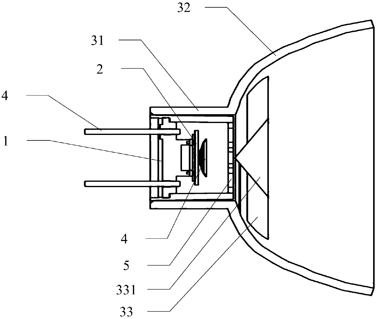
[0029] See figure 1 , the ultrasonic transducer includes a housing, a support ring 1, a piezoelectric wafer 2, pins 3, a tapered resonant disk 4 and a wire mesh cover 5, and the housing includes an accommodating cavity 31, a horn 32 and a phase plug 33, the housing is a horn with a phase plug, the accommodating cavity 31 is connected to the horn 32, the phase plug 33 is set in the horn 32, and the support ring 1 is set in the accommodating cavity 31, one side of th...

Embodiment 2

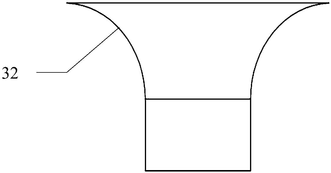
[0040] See image 3 The difference between the second embodiment and the first embodiment is that the horn is basin-shaped and divergent, and the phase plug horn can expand the beam angle of the sound wave to make it detect a wider range.


PUM


Abstract

The invention discloses an ultrasonic transducer. The ultrasonic transducer comprises a shell, a supporting ring, a piezoelectric wafer, pins, a conical resonance disc and a metal wire mesh enclosure.The shell comprises an accommodating cavity, a horn and a phase plug; the accommodating cavity is connected with the loudspeaker; the phase plug is arranged in the horn; the supporting ring is arranged in the accommodating cavity; a piezoelectric wafer, a conical resonance disc and a metal wire mesh cover are sequentially arranged on one side of the supporting ring; wherein the piezoelectric wafer is arranged on the supporting ring in a supporting mode, the conical resonance disc is arranged on the piezoelectric wafer, the metal wire mesh enclosure is connected with the cavity wall of the accommodating cavity, and the pin is arranged on the other side of the supporting ring and penetrates through the supporting ring to be connected with the piezoelectric wafer. The horn structure of the shell improves the directivity of an ultrasonic wave beam and the acoustic load characteristic of a vibration part of the transducer, and ultrasonic waves passing through the horn have a specific wavebeam angle and are radiated into air. The invention also provides an ultrasonic ranging module.

Description

technical field [0001] The invention relates to the field of ultrasonic ranging, in particular to an ultrasonic transducer and an ultrasonic ranging module. Background technique [0002] Ultrasound is a useful technique for odometry or distance measurement of objects of interest. Ultrasonic ranging involves the emission of ultrasound waves from an ultrasound source towards an object of interest. Ultrasound is reflected from the object of interest and transmitted back to the source of the ultrasound. Since sound has a relatively constant velocity, the travel time for an ultrasound pulse to reflect from the object of interest and return to the source of ultrasound is proportional to the distance between the source and the object. Thus, by measuring the travel time of the ultrasound pulse, the distance can be determined. [0003] When ultrasonic ranging is applied to height measurement, an ultrasonic height measuring instrument is produced, which replaces the traditional mec...

Claims


Application Information

Patent Timeline
Patent Type & Authority Applications(China)
IPC IPC(8): G01S7/521G01S15/08
CPCG01S7/521G01S15/08
Inventor 于东亮王丽秦绪阳闾灿
Owner SENSEED TECH CO LTD
Why Eureka
Eureka Blog
Learn More