Cleaning equipment for urban road
A road and equipment technology, which is applied in the field of cleaning equipment for urban roads, can solve the problems of decontamination, cleaning, maintenance and replacement of squatting or lying on the ground, and achieves convenient operation, easy decontamination, and improved efficiency and quality Effect
- Summary
- Abstract
- Description
- Claims
- Application Information
AI Technical Summary
Problems solved by technology
Method used
Image
Examples
Embodiment
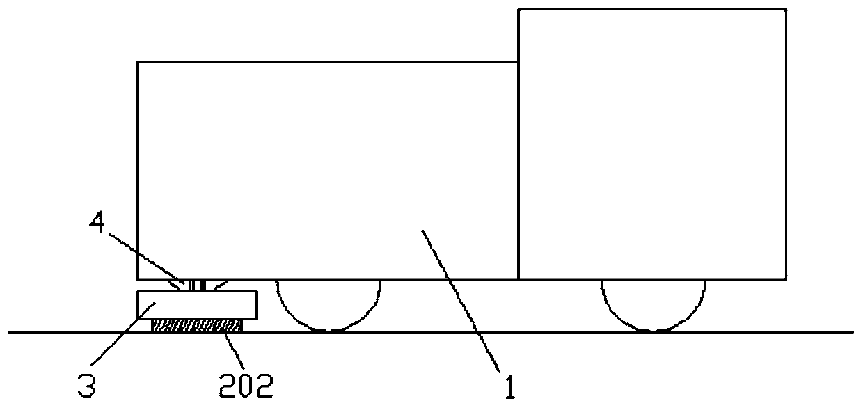
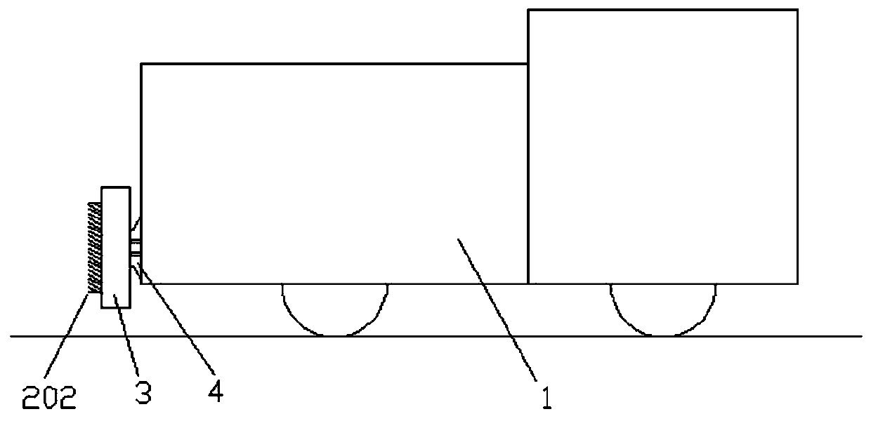
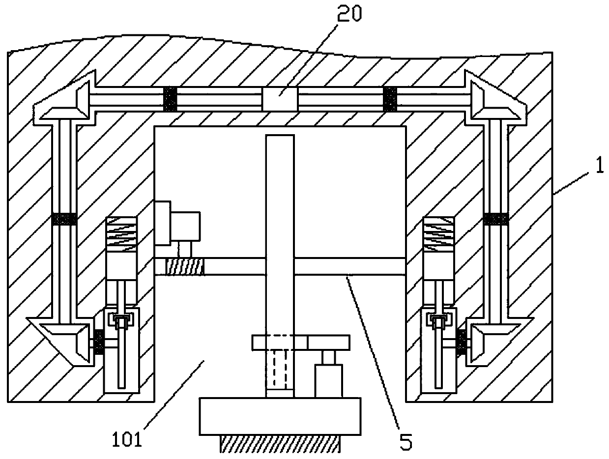
[0035] A kind of cleaning equipment for urban roads, with reference to Figure 1-Figure 7 As shown, it generally includes the following structure:
[0036]Including the mobile car body 1, a cuboid-shaped cavity 101 is provided at the bottom of the tail end of the mobile car body 1, and a movable cleaning mechanism is arranged in the cavity 101. The cleaning mechanism includes a cleaning disc brush 2 for cleaning the ground, The disc brush housing 3 and the rotating disc body 4, the disc brush housing 3 includes a concave cavity 301 towards the ground side, the cleaning disc brush 2 is arranged in the concave cavity 301 of the disc brush housing 3, and the back of the disc brush housing 3 is fixed Connected to the sides of the rotating disk body 4, the rotating disk body 4 is vertically arranged in the middle of the cavity 101, and the rotation center of the rotating disk body 4 is pierced with a rotating horizontal axis 5, and the two ends of the rotating horizontal axis 5 are...
Embodiment approach 1
[0045] Such as Figure 8 As shown, the driving mechanism includes a rotating shaft 24, a first spur gear 25, a second spur gear 26 and a second driving motor 27, and one end of the rotating shaft 24 is fixedly connected to the center of rotation of the brush disc 201 back side of the cleaning disc brush 2, and the rotating shaft 24 Through the disc brush housing 3, a T-shaped slot 401 is opened on the rotating disc body 4 along the radial position direction, the rotating shaft 24 extends into the T-shaped slot 401, and the top end of the rotating shaft 24 is rotated and inserted in the rotating disc body 4 Among them, the rotation center of the above-mentioned first spur gear 25 is fitly sleeved on the rotating shaft 24 of the T-shaped slot 401, and the side part of the second drive motor 27 is fixedly installed on the rotating disc body 4 through brackets and bolts, and the above-mentioned second The center of rotation of the spur gear 26 is installed on the power output end ...
Embodiment approach 2
[0047] Such as Figure 9 As shown, the driving mechanism includes a rotating shaft 24, a second worm gear 30 and a second driving motor 27, one end of the rotating shaft 24 is fixedly connected to the rotation center of the back side of the brush disc 201 of the cleaning disc brush 2, and the rotating shaft 24 runs through the disc brush housing 3, A bar-shaped slot 402 is provided on the rotating disk body 4 along the radial position direction, the rotating shaft 24 extends into the bar-shaped slot 402, and the second worm 31 is arranged in the rotating shaft 24 in the bar-shaped slot 402 , the top of the rotating shaft 24 is rotated and inserted in the rotating disk body 4, the second drive motor 27 is fixedly mounted on the back of the rotating disk body 4, and the rotation center of the second worm wheel 30 is connected to the power output end of the second driving motor 27 , the second worm gear 30 and the second worm screw 31 are meshed for transmission connection, and t...
PUM
 Abstract
Description
Claims
Application Information
 - R&D
- Intellectual Property
- Life Sciences
- Materials
- Tech Scout
- Unparalleled Data Quality
- Higher Quality Content
- 60% Fewer Hallucinations
Browse by: Latest US Patents, China's latest patents, Technical Efficacy Thesaurus, Application Domain, Technology Topic, Popular Technical Reports.
© 2025 PatSnap. All rights reserved.Legal|Privacy policy|Modern Slavery Act Transparency Statement|Sitemap|About US| Contact US: help@patsnap.com


