
Magnetic levitation vertical shaft disc type coreless wind driven generator

A wind power generator and magnetic levitation technology, which is applied in wind power generators, wind power generators at right angles to the wind direction, combination of wind power motors, etc., can solve problems such as high loss, lack of heat dissipation measures and shock absorption measures, and reduced service life of motors , to achieve the effects of convenient manufacture, easy start-up with breeze, and low eddy current loss

Inactive Publication Date: 2020-05-15
NANJING UNIV OF INFORMATION SCI & TECH
View PDF9 Cites 5 Cited by
  • Summary
  • Abstract
  • Description
  • Claims
  • Application Information

AI Technical Summary

Problems solved by technology

[0005] In order to reduce the weight of the motor, the Chinese Patent Publication No. CN206259836U, titled "A Combination Sinusoidal Disk Type Ironless Permanent Magnet Wind Power Generator" adopts a hollow shaft and an ironless disk stator structure. Although such a structure can reduce Part of the weight, but still failed to get rid of the dependence on traditional bearings, the loss is still not small
In addition, without heat dissipation measures and shock absorption measures, the service life of the motor will be greatly reduced

Method used


Image

  • Magnetic levitation vertical shaft disc type coreless wind driven generator
  • Magnetic levitation vertical shaft disc type coreless wind driven generator
  • Magnetic levitation vertical shaft disc type coreless wind driven generator

Examples


Embodiment

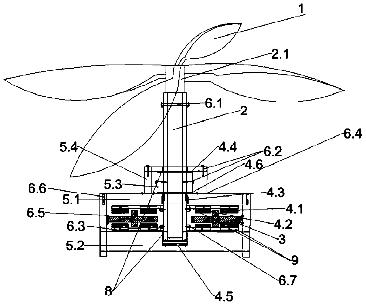
[0034] Such as figure 1 As shown, a magnetic levitation vertical shaft disk coreless wind power generator in this embodiment includes a blade device, a stator device and a rotor device; the blade device includes a blade shaft 2.1 and a blade 1 fixed on the top of the blade shaft 2.1; In this embodiment, the blade 1 is ear-shaped and fixed on the blade shaft 2.1 by bolts. The blade 1 is made of FRP composite material and made into four twisted blades. There is a certain space in the middle of the blades; compared with traditional blades, ear-shaped blades It has the characteristics of large positive force area and small reverse force area, so it has the advantage of large rotational torque.

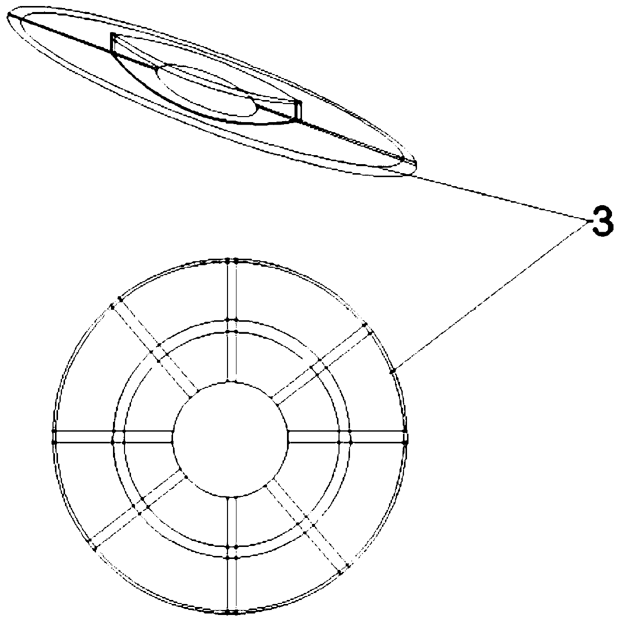
[0035]The stator device in this embodiment includes a shell and a disk-shaped non-magnetically conductive bracket 3 fixed on the inside of the shell. The shell includes an upper shell 5.1 and a lower shell 5.2 that are fixedly connected to each other through a sixth bolt 6.6. There is a c...


PUM


Abstract

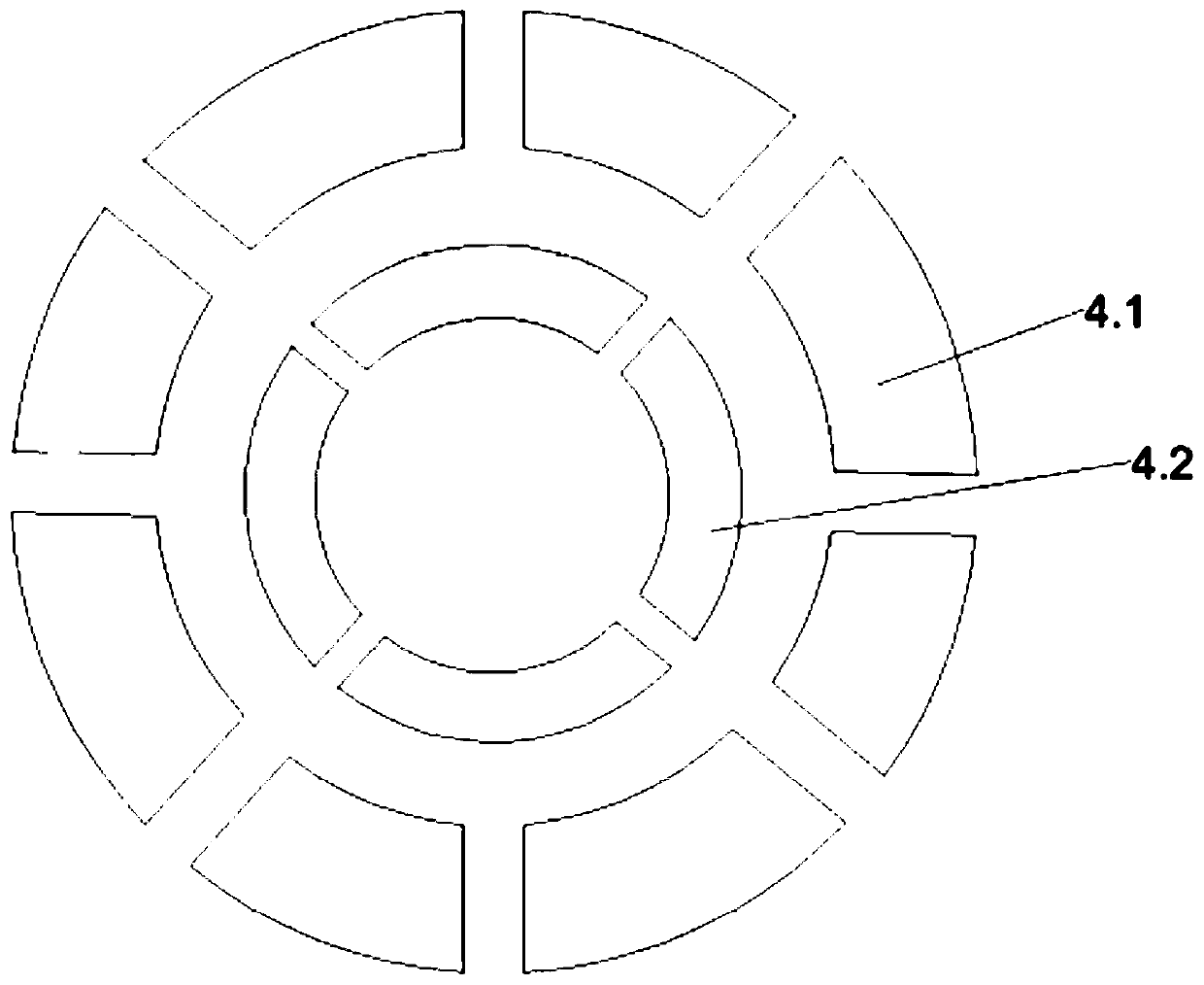
The invention relates to a magnetic levitation vertical shaft disc type coreless wind driven generator. The magnetic levitation vertical shaft disc type coreless wind driven generator comprises a blade device, a stator device and a rotor device; the blade device comprises a blade shaft and blades fixed to the top of the blade shaft, the stator device comprises an outer shell and a disk-shaped non-magnetically conductive support fixed to the inner side of the outer shell, the support is wound with a coil, the rotor device comprises a hollow magnetic levitation rotating shaft, a magnetic conductive disc fixed on the magnetic levitation rotating shaft and an annular magnetic pole fixed on the magnetic conductive disc, the lower end of the blade shaft is fixed to the upper end of the magneticlevitation rotating shaft, the lower end of the magnetic levitation rotating shaft extends into the outer shell and is rotatably connected with the outer shell, the magnetic levitation rotating shaftand the outer shell are provided with mutually matched magnetic pole pairs at positions close to each other, the magnetic pole pairs generate an upward suspension force on the magnetic levitation rotating shaft, and the coil on the support cuts the magnetic induction line of the annular magnetic pole during rotation of the rotor device to generate an induced current. The generator can be started with breeze, is low in loss, light in weight, small in vibration, low in manufacturing cost and long in service life.

Description

technical field [0001] The invention relates to a wind power generator, in particular to a permanent magnet wind power generator using a magnetically suspended hollow rotating shaft and a disc-shaped non-magnetic support. Background technique [0002] Most of the impeller shafts of existing wind turbines are arranged horizontally and are generally supported by bearings. The parts are worn during operation, and the requirements for bearings are high, which increases the production cost. In addition, due to the large rotation resistance, the power generation efficiency is low or even impossible at low wind speeds. Power generation; operation and maintenance may also require high-altitude operations, which is dangerous and difficult to construct and install, which is not conducive to home use. In recent years, vertical axis wind turbines have developed rapidly in terms of wind-solar complementary street lights, charging piles, and household electricity. However, it is difficul...

Claims


Application Information

Patent Timeline
IPC IPC(8): F03D9/25F03D3/00F03D3/06F03D80/00F03D80/70H02K16/02
CPCF03D9/25F03D3/005F03D3/061F03D80/00F03D80/70H02K16/02F05B2280/4003F03D3/062Y02E10/74Y02P70/50
Inventor 冯亮亮曹永娟
Owner NANJING UNIV OF INFORMATION SCI & TECH
Learn More