Laser speckle eliminating device and laser projection equipment

A technology of laser projection and speckle dissipation, applied in the field of optics, can solve the problems of increased laser projection display system loss, complex structure, and scattered scattering

Active Publication Date: 2020-05-15
QINGDAO HISENSE LASER DISPLAY CO LTD
View PDF5 Cites 1 Cited by
  • Summary
  • Abstract
  • Description
  • Claims
  • Application Information

AI Technical Summary

Problems solved by technology

[0004]The technique's reliance on mechanical vibration increases losses in the laser projection display system due to the multiple independent non-correlated speckle images produced by mechanically vibrating scatterers, and complex structure
In addition, due to the chaotic scattering of light by ordinary scattering media, thin scattering media have the problem of dark edges in the center of the outgoing light field, and thick scattering media have too much light loss, so it is necessary to rely on specially designed uniform light elements to correct the light passing through the scattering media. Homogenization, and the effect of suppressing laser speckle depends on the design of the homogenization element

Method used


Image

  • Laser speckle eliminating device and laser projection equipment
  • Laser speckle eliminating device and laser projection equipment
  • Laser speckle eliminating device and laser projection equipment

Examples


Embodiment 1

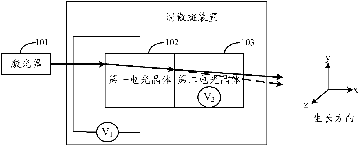
[0025] see figure 1 , is a schematic structural diagram of a laser speckle elimination device provided in an embodiment of the present application. As shown in the figure, the laser speckle elimination device includes a laser 101 , and a first electro-optic crystal 102 and a second electro-optic crystal 103 are arranged on the transmission path of the laser light emitted by the laser 101 .

[0026] The laser light emitted by the laser 101 is incident on the first electro-optic crystal 102, is incident on the second electro-optic crystal 103 after being transmitted through the first electro-optic crystal 102, and is emitted from the second electro-optic crystal 103 after being transmitted in the second electro-optic crystal 103. The light outlet exits.

[0027] Wherein, the first electro-optic crystal 102 or the second electro-optic crystal 103 is potassium tantalum niobate crystal (KTa 1-X Nb X o 3 , KTN), or both electro-optic crystals are potassium tantalum niobate cryst...

Embodiment 3

[0061] Optionally, in the laser speckle-eliminating device provided in the embodiment of the present application, a first phase plate 104 may also be disposed between the first electro-optic crystal and the second electro-optic crystal. like Figure 7 , which is a schematic structural diagram of the laser speckle elimination device provided in the embodiment of the present application. As shown in the figure, the first phase plate 104 is located between the first electro-optic crystal 102 and the second electro-optic crystal 103, and is used to make the polarization direction of the laser beam emitted from the first electro-optic crystal 102 coincide with the growth direction of the second electro-optic crystal 103. Vertical or nearly vertical, so as to avoid the problem of laser light loss caused by birefringence in the second electro-optic crystal 103 and only part of the light energy is deflected. Wherein, the first electro-optic crystal 102 , the first phase plate 104 and...

Embodiment 4

[0071] Based on the same technical idea, an embodiment of the present application further provides a laser projection device, which includes the laser speckle elimination device in the foregoing embodiments.

[0072] like Figure 9 Shown is a schematic structural diagram of a laser projection device provided in an embodiment of the present application. refer to Figure 9 As shown, the laser projector includes a laser 901 , a laser speckle elimination device 902 , a light modulation device 903 and a lens 904 .

[0073] The laser beam emitted by the laser 901 provides illumination for the light modulation device 903 after passing through the laser speckle elimination device 902, and the light modulation device 903 modulates the laser beam, and outputs it to the lens 904 for imaging, and projects it to the projection medium 905 to form a projection picture .

[0074] The above-mentioned light modulation device 903 is used to modulate the laser beam emitted by the laser speckle...


PUM


Abstract

The invention discloses a laser speckle eliminating device and laser projection equipment. The laser speckle eliminating device comprises a first electro-optical crystal and a second electro-optical crystal, laser emitted by the laser device enters the first electro-optical crystal, enters the second electro-optical crystal after being transmitted by the first electro-optical crystal, and exits from a light outlet of the second electro-optical crystal after being transmitted in the second electro-optical crystal. The growth directions of the first electro-optical crystal and the second electro-optical crystal are respectively perpendicular to the incident direction of a laser beam incident to the first electro-optical crystal, and the growth directions of the first electro-optical crystaland the second electro-optical crystal are perpendicular to each other; the first electro-optical crystal and the second electro-optical crystal are respectively controlled by a voltage signal, and the voltage applied to the first electro-optical crystal and the second electro-optical crystal changes with time, so that the refractive indexes of the first electro-optical crystal and the second electro-optical crystal change with time.

Description

technical field [0001] The invention relates to the field of optical technology, in particular to a laser speckle extinction device and laser projection equipment. Background technique [0002] In recent years, projection display technology has developed very rapidly, and people's requirements for display are also increasing. High brightness, high color saturation, and wide-area display have become the basic requirements for display. As a potential light source for next-generation projection displays, lasers have different characteristics compared with ordinary light sources. For example, lasers have better monochromaticity, better directionality, and higher brightness than ordinary light sources. [0003] Laser is a highly coherent light source. During the laser projection display process, it will produce very serious scattering phenomenon to form laser speckle. Laser speckle seriously affects the quality of laser projection display. In the prior art, laser speckle suppres...

Claims


Application Information

Patent Timeline
Patent Type & Authority Applications(China)
IPC IPC(8): G02F1/29G02B27/48G03B21/20
CPCG02F1/29G02B27/48G03B21/2033
Inventor 宋丽培王静茹郭汝海刘显荣田有良
Owner QINGDAO HISENSE LASER DISPLAY CO LTD
Why Eureka
Try Eureka