Supercharge Your Innovation With Domain-Expert AI Agents!

Biogas digester

A biogas digester and gas transmission technology, applied in the field of biogas digesters, can solve problems such as waste of resources, decline in biogas quality or yield, and inconvenient discharge of sludge, and achieve the effect of avoiding waste and yield decline.

Inactive Publication Date: 2020-05-19
赵文
View PDF0 Cites 0 Cited by
  • Summary
  • Abstract
  • Description
  • Claims
  • Application Information

AI Technical Summary

Problems solved by technology

[0003] In order to build a new countryside, most rural households now build biogas digesters. Through the construction of biogas digesters, the natural environment in the countryside can be relieved, and the associated products of biogas can also be used for crop planting and fertilization to increase farmers’ income. However, household There are still some defects in the biogas digester. Because the biogas digester is in a sealed environment, when the biogas is continuously generated, the air pressure in the biogas digester will increase accordingly. If the pressure is not released in time, the internal pressure of the biogas digester will be too high and damaged. However, depressurization requires the discharge of biogas, resulting in a waste of resources. In addition, excessive raw materials in the biogas tank will cause a decrease in the quality or output of biogas. Therefore, it is necessary to carry out regular desilting of the interior of the biogas tank to keep the space in the biogas tank always spacious. To ensure the output of biogas, but the current biogas tank is not convenient to discharge silt, in order to solve the above technical problems, the present invention proposes a biogas tank

Method used


Image

  • Biogas digester
  • Biogas digester
  • Biogas digester

Examples


Embodiment Construction

[0022] In order to make the technical means, creative features, goals and effects achieved by the present invention easy to understand, the present invention will be further described below in conjunction with specific embodiments.

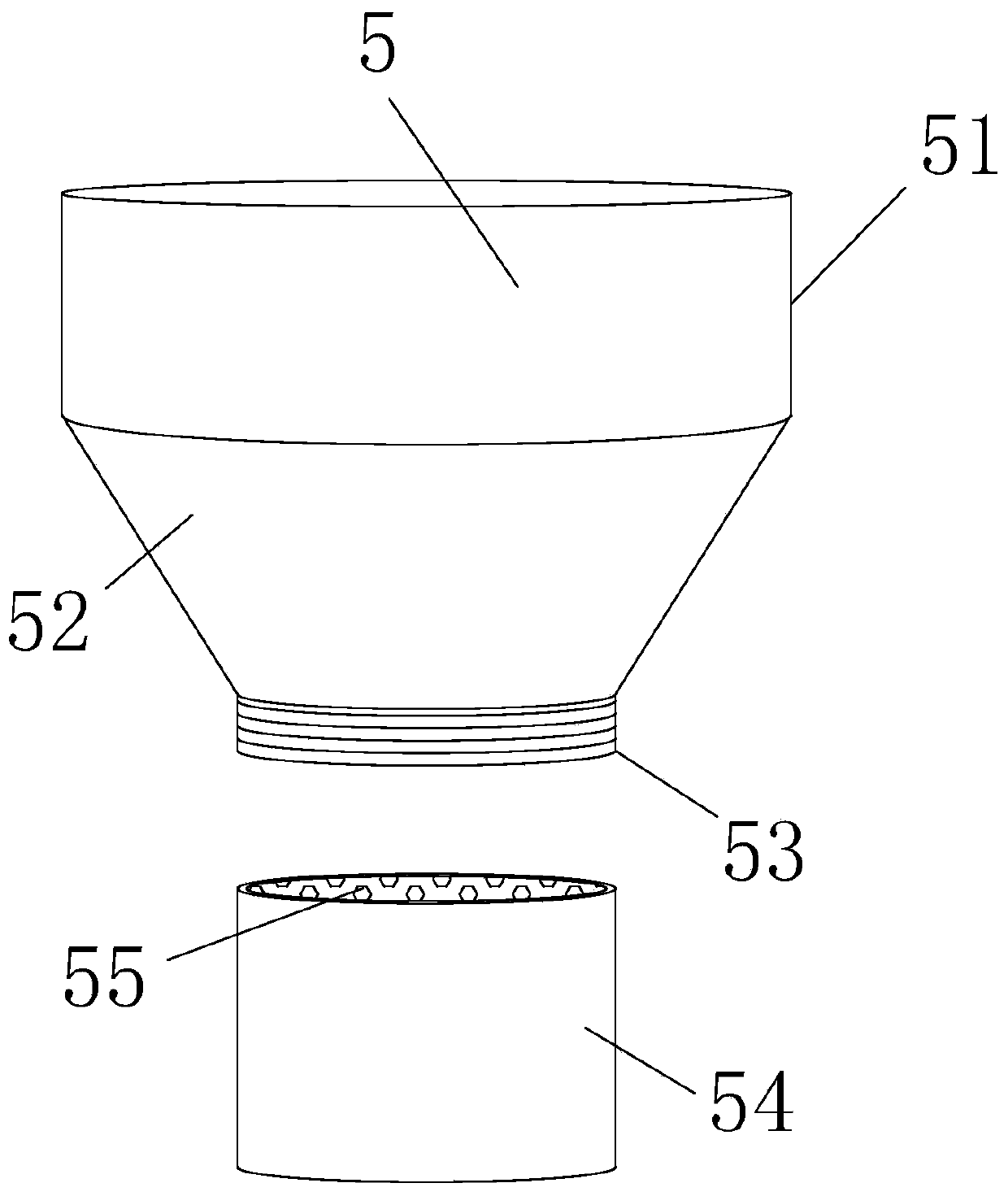
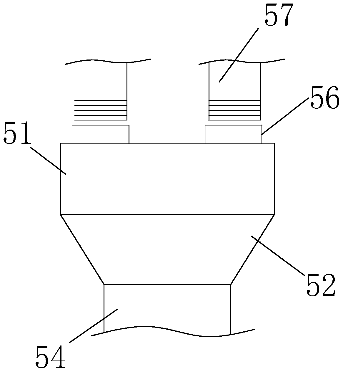
[0023] Such as Figure 1-Figure 6 As shown, a biogas digester includes a biogas digester 1, the top of the biogas digester 1 is connected with a top cover 2, and one side of the top cover 2 is fixedly connected with a barometer 3, and the top of the top cover 2 is close to the barometer One side of the top cover 2 is fixedly connected with a liquid level gauge 4, the middle of one side wall of the top cover 2 is fixedly connected with a feed structure 5, and the side of the top cover 2 away from the liquid level gauge 4 is fixedly connected with a gas transmission Structure 6, a pressure relief structure 7 is fixedly connected to the side wall on the same side of the top cover 2 and the gas transmission structure 6, and a dredging structure 8 is f...


PUM


Abstract

The invention relates to the field of biogas digesters, and in particular to a biogas digester, wherein a feeding structure is fixedly connected in the middle of one side wall of a top cover; a gas conveying structure is fixedly connected to one side, far away from a liquid level meter, of the top cover; a dredging structure is fixedly connected to the lower part of one side wall of the methane tank; and a temporary storage box is fixedly connected to one end, far away from the biogas digester, of the dredging structure. According to the invention, feeding is more convenient through arrangement of the feeding structure; a filter screen structure is arranged in the feeding structure, so that materials can be filtered, impurities can be prevented from entering the methane tank, and influenceon fermentation of the materials can be avoided; materials in different areas can be collected through splicing pipes; gas pressure in the methane tank can be released through arrangement of a pressure release structure, so that the problem of the biogas digester caused by overhigh gas pressure in the biogas digester can be avoided; discharged methane can be stored through arrangement of a storage tank; and a control valve is connected with the gas transmission structure to ensure that the methane cannot be dissipated and wasted, and when being needed, the methane can be extracted through a gas suction pump and is discharged through an output pipe.

Description

technical field [0001] The invention relates to the field of biogas digesters, in particular to a biogas digester. Background technique [0002] Biogas is a kind of heatable gas in nature. It is produced by microbial fermentation under certain temperature, humidity and pH conditions. It is often called biogas because it is often distributed in swamps, lakes and ponds. . With the development of our country's economy and social progress, the life of urban residents has been further improved, but there are still many problems in the life of rural residents. This requires the development of rural ecological agricultural production methods, the improvement of the rural environment, and the grand goal of increasing farmers' income. Among them Comprehensive utilization of biogas digesters is an important way to change the rural environment. The construction of a biogas digester can be used for about 20 years. Comprehensive utilization of biogas digesters can not only save energy, ...

Claims


Application Information

Patent Timeline
Patent Type & Authority Applications(China)
IPC IPC(8): C12M1/107C12M1/34C12M1/12C12M1/00
CPCC12M21/04C12M23/36C12M23/38C12M33/14C12M41/40C12M41/44
Inventor 赵文李亚利任磊
Owner 赵文
Features
  • R&D
  • Intellectual Property
  • Life Sciences
  • Materials
  • Tech Scout
  • Unparalleled Data Quality
  • Higher Quality Content
  • 60% Fewer Hallucinations
Learn More