
Gas drainage pump stable operation dual-loop control system

A double-loop control and gas extraction technology, applied in pump control, gas discharge, mining equipment, etc., can solve problems that affect the stable operation of equipment, fail to meet requirements, and cannot monitor and control real-time on-site data

Pending Publication Date: 2020-05-19
SHAANXI SHAANXI COAL HANCHENG MINING CO LTD +1
View PDF0 Cites 0 Cited by
  • Summary
  • Abstract
  • Description
  • Claims
  • Application Information

AI Technical Summary

Problems solved by technology

[0004] One is to determine the vacuum degree of the circulating pump. When the water volume is small, the vacuum degree is small and cannot meet the requirements, which affects the pumping efficiency; when the water volume is large, the vacuum degree can meet the requirements, but the motor load current increases;
[0005] The second is to water-cool the pump body. A large amount of water will take away more heat and the temperature of the pump body will be low; a small amount of water will take away less heat, and the equipment will generate heat, which will affect the stable operation of the equipment.
[0007] According to the comprehensive consideration of the measured negative pressure, flow rate, temperature, gas concentration and other parameters, the in-situ, manual and manual operation methods are used to adjust the water intake of the water ring pump. It is impossible to grasp the operating status of the equipment in real time, and it is impossible to monitor and control the field data in real time. , the level of mine modernization management is low

Method used


Image

  • Gas drainage pump stable operation dual-loop control system
  • Gas drainage pump stable operation dual-loop control system
  • Gas drainage pump stable operation dual-loop control system

Examples


Embodiment Construction

[0018] The following will clearly and completely describe the technical solutions in the embodiments of the present invention with reference to the accompanying drawings in the embodiments of the present invention. Obviously, the described embodiments are only some, not all, embodiments of the present invention. Based on the embodiments of the present invention, all other embodiments obtained by persons of ordinary skill in the art without making creative efforts belong to the protection scope of the present invention.

[0019] In the present invention, the term "comprising", "comprising" or any other variation thereof is intended to cover a non-exclusive inclusion such that a process, method, article or apparatus comprising a set of elements includes not only those elements, but also includes none. other elements specifically listed, or also include elements inherent in such a process, method, article, or apparatus. without further restrictions. An element defined by the phr...


PUM


Abstract

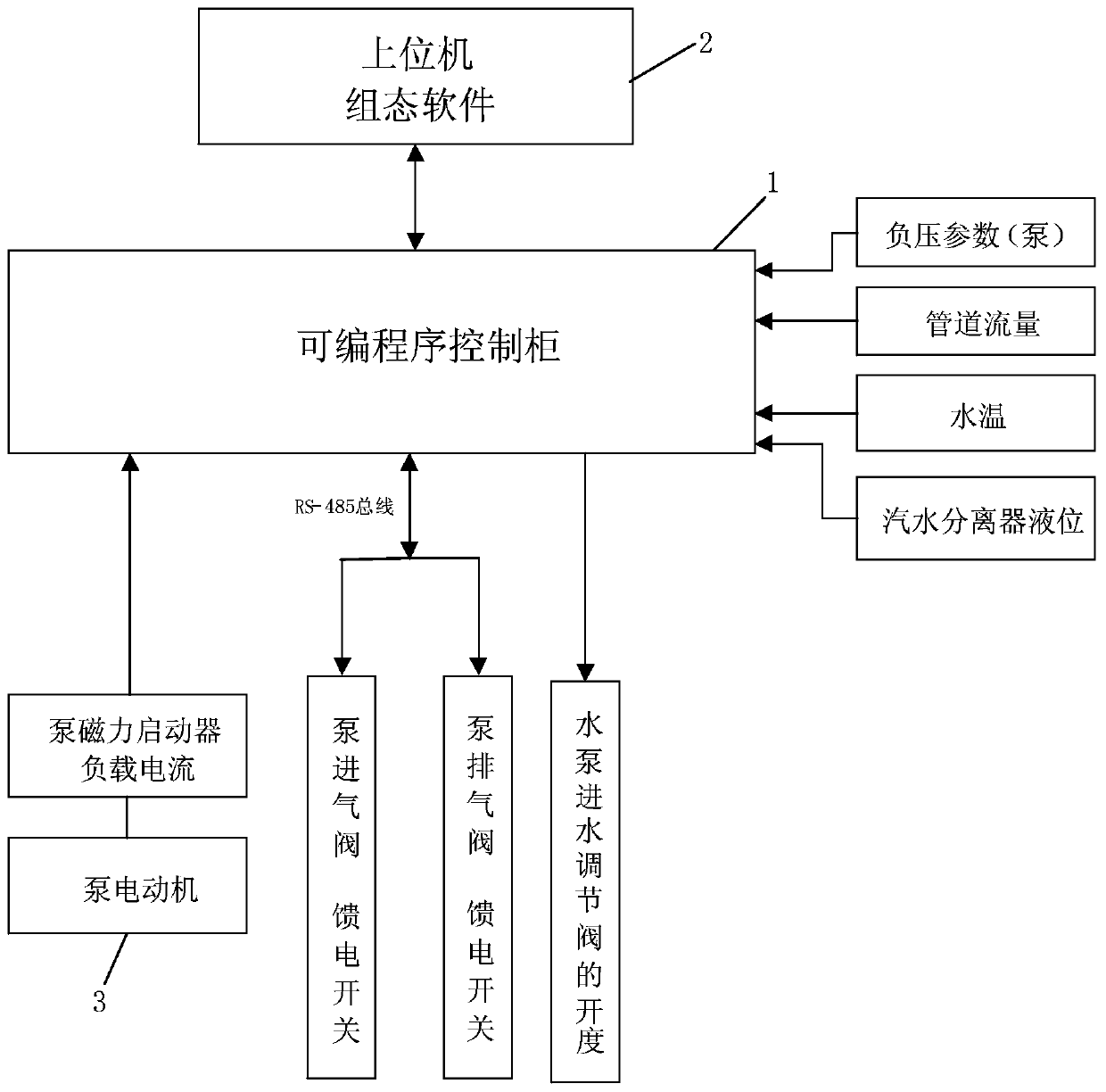
The invention provides a gas drainage pump stable operation dual-loop control system. The system comprises a programmable control cabinet, an upper computer, a gas water circulation pump, a pump motorand a water gas separator, wherein the output end of the pump motor is connected to the power input end of the gas water circulation pump via a pump reducer, a water gas outlet of the gas water circulation pump is connected with a water gas inlet of the water gas separator, a water outlet of the water gas separator is connected with a water inlet of a cooling water tank, a water outlet of the cooling water tank is connected with a water inlet of a high-level water tank, a water outlet of the high-level water tank is connected with a water inlet of the gas water circulation pump through a water inlet pipeline, a PLC constant pressure control box and a position type electric regulating valve are arranged on the connecting pipeline between the gas water circulation pump and the high-level water tank, and a pipeline flowmeter is arranged on an automatic underground gas drainage pipeline. According to the system, various working states, and operating parameters of a gas drainage pump are truly monitored, remote control operation can be realized, unattended operation of the underground dangerous environment is achieved, energy is saved, the labor intensity is reduced, the operation costis reduced, and the service life of equipment is prolonged.

Description

technical field [0001] The patent of the invention belongs to the technical field of gas drainage, and specifically relates to a complex adjustment control system for stable operation of a gas drainage pump. Background technique [0002] The main function of the gas drainage pump station is to collect the capillary drainage pipelines arranged in the underground coal seam and empty coal seam, and then lead to the ground drainage pump station through the main pipeline. The gas is pumped through the pipeline to the ground for discharge or sent to the gas power plant for gas utilization. When the gas drainage pump station is working, first open the exhaust valve, start the pump motor, the pump motor runs to drive the reducer to rotate, thereby driving the water circulation pump to work, then open the intake valve; open the water intake valve of the water circulation pump, the water circulation pump rotates , the water entering the cavity is rotated and dispersed until the casin...

Claims


Application Information

Patent Timeline
Patent Type & Authority Applications(China)
IPC IPC(8): F04B49/06F04B49/22E21F7/00
CPCE21F7/00F04B49/065F04B49/22
Inventor 李民郭毅军孙博倪云峰李昌聪
Owner SHAANXI SHAANXI COAL HANCHENG MINING CO LTD
Learn More