Garbage drying device for garbage incineration power generation

A technology of waste incineration and drying equipment, which is applied in the direction of drying, drying machines, heating devices, etc., which can solve the problems of increasing the cost of incinerating waste, too simple rotating rod, and reducing the dehydration effect of waste, so as to facilitate discharge and improve Rotation effect, effect of improving dehydration quality

Active Publication Date: 2020-05-19
湖南天桥环境科技有限公司
View PDF5 Cites 2 Cited by
  • Summary
  • Abstract
  • Description
  • Claims
  • Application Information

AI Technical Summary

Problems solved by technology

Since the garbage contains a lot of water and has a low calorific value, additional combustion accelerants are required to support the combustion during incineration, which greatly increases the cost of incinerating garbage; before garbage incineration, it is usually necessary to dehydrate the garbage and then dry it. Sometimes the garbage cannot be fully rotated and dehydrated, and the rotating rod is too simple, which reduces the dehydration effect of the garbage

Method used


Image

  • Garbage drying device for garbage incineration power generation
  • Garbage drying device for garbage incineration power generation
  • Garbage drying device for garbage incineration power generation

Examples


Embodiment 1

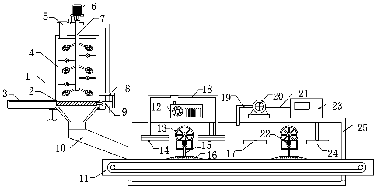
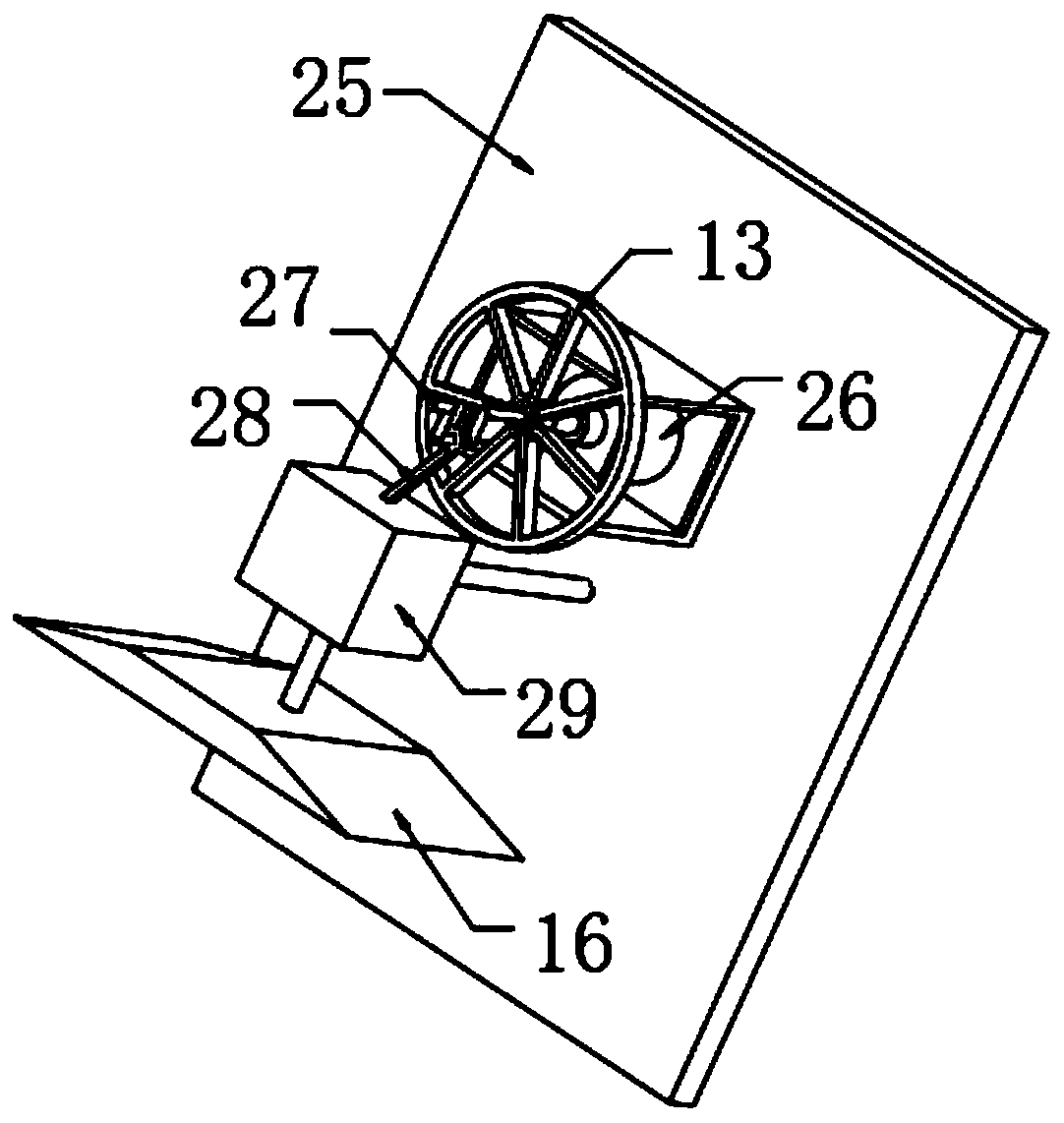
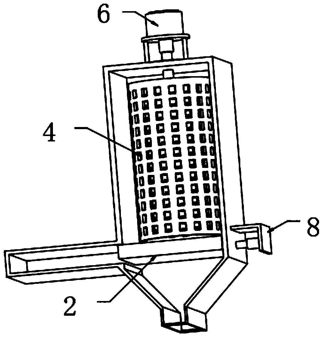
[0031] refer to Figure 1-4 , a garbage drying device for waste incineration power generation, comprising a dehydration box 1 and a drying box 25, the inner wall of the dehydration box 1 is welded with a dehydration cylinder 4, and the top outer wall of the dehydration box 1 is fixed with a first motor 6 by screws, the second The output shaft of a motor 6 is connected with the first rotating rod 7 through a shaft coupling, and the outer wall of the first rotating rod 7 is welded with equidistantly distributed stirring plates 31, and the outer walls of the stirring plate 31 are welded with equidistantly distributed stirring plates 31. Protrusion, the outer wall of the first rotating rod 7 and the inner wall of the dehydration cylinder 4 are welded with a connecting rod 30, and the outer wall of the connecting rod 30 is connected with a runner 32 through a bearing, and the outer wall of one side of the dehydration box 1 is fixed with a connecting box 3 by screws , and one side o...

Embodiment 2

[0038] refer to Figure 5 , a garbage drying device for waste incineration power generation, also includes a purifier 34 fixed to the outer wall of one side of the dehydration box 1 by screws, the input end of the purifier 34 and the inner wall of one side of the dehydration box 1 are connected by the same flange Airway 33.

[0039] Connect the equipment to the power supply, put the garbage into the dehydration cylinder 4 from the feed port 15, turn on the first motor 6, and the first motor 6 drives the first rotating rod 7 to rotate, and then the stirring plate 31 and the runner 32 can be rotated. Fully rotate and dehydrate the garbage. After the dehydration is completed, connect the hydraulic rod 9 to the hydraulic system. When the length of the hydraulic rod 9 is adjusted, the baffle plate 2 is pushed out, and the garbage is discharged from the feeding chute 10. The conveying table 11 is opened, and the garbage starts to be conveyed , turn on the hot air blower 12, dry the...


PUM


Abstract

The invention belongs to the technical field of garbage incineration, and particularly relates to a garbage drying device for garbage incineration power generation. For solving the problem of insufficient dehydration, the following scheme is provided: the garbage drying device comprises a dehydration box and a drying box, a dehydration cylinder is arranged on the inner wall of the dehydration box,the outer wall of the top of the dehydration box is provided with a first motor, an output shaft of the first motor is provided with a first rotating rod, stirring plates distributed at equal distances are arranged on the outer wall of the first rotating rod, protrusions distributed at equal distances are arranged on the two sides of the outer walls of the stirring plates, connecting rods are arranged on the outer wall of the first rotating rod and the inner wall of the dehydration cylinder, and the outer walls of the connecting rods are connected with rotating wheels through bearings. Sincethe stirring plates, the connecting rods and the rotating wheels, the multiple protrusions are arranged on the outer walls of the stirring plates, the contact area between garbage and the stirring plates is increased, garbage rotation can be accelerated when garbage is stirred, the rotating wheels can be rotated in different directions, the rotating effect is improved, and therefore garbage dehydration quality is improved.

Description

technical field [0001] The invention relates to the technical field of waste incineration, in particular to a waste drying device for waste incineration to generate electricity. Background technique [0002] Garbage is a waste item that loses its use value and cannot be used, and is an important link in the material cycle. A solid or fluid substance that is unwanted or useless. In densely populated cities, garbage disposal is a headache. [0003] Incineration treatment is one of the main methods of garbage disposal. This method is to put the garbage in a high-temperature furnace to fully oxidize the combustible components. The heat generated is used for power generation and heating. Since the garbage contains a lot of water and has a low calorific value, it is necessary to use additional combustion accelerants to support the combustion during incineration, which greatly increases the cost of incinerating garbage; before garbage incineration, it is usually necessary to dehy...

Claims


Application Information

Patent Timeline
IPC IPC(8): F26B5/08F26B15/18F26B21/00F26B23/04F26B25/04A61L2/10F23G5/04
CPCA61L2/10F23G5/04F26B5/08F26B15/18F26B21/001F26B23/04F26B25/04
Inventor 凌英周生光黄亚飞
Owner 湖南天桥环境科技有限公司
Why Eureka
Try Eureka