Surface energy gradient bionic liquid absorption core and application thereof

A liquid-absorbing core, the next bionic technology, applied in the direction of lighting and heating equipment, indirect heat exchangers, etc., can solve the problems of insufficient capillary suction, back heat conduction, etc., to solve the problem of insufficient capillary suction and reduce flow Effect of resistance, good engineering application significance

Active Publication Date: 2020-05-19
XIAMEN UNIV
View PDF5 Cites 3 Cited by
  • Summary
  • Abstract
  • Description
  • Claims
  • Application Information

AI Technical Summary

Problems solved by technology

[0005] The purpose of the present invention is to overcome the deficiencies of the prior art, provide a surface energy gradient bionic liquid-absorbent core and its application, and solve the problems of insufficient capillary suction and back heat conduction in the above-mentioned background technology

Method used


Image

  • Surface energy gradient bionic liquid absorption core and application thereof
  • Surface energy gradient bionic liquid absorption core and application thereof
  • Surface energy gradient bionic liquid absorption core and application thereof

Examples


Embodiment 1

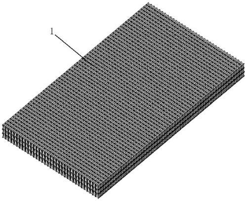
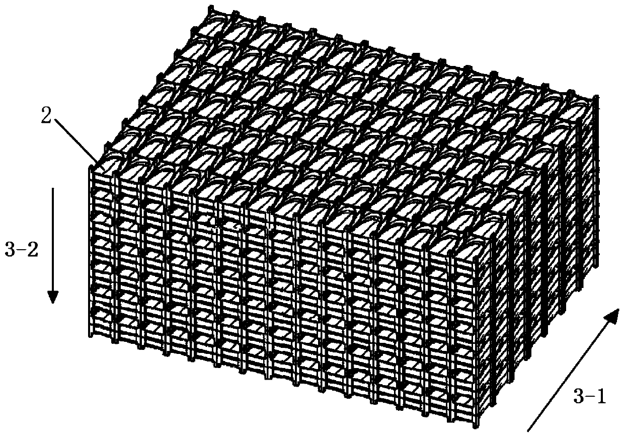
[0030] A kind of surface energy gradient bionic liquid-absorbent core 1 of the present embodiment, such as figure 1 and 2 , including several bionic units 2 arranged in a three-dimensional array.

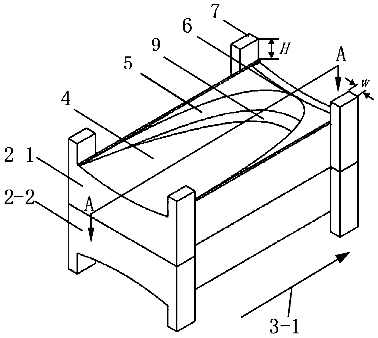
[0031] The bionic unit 2 is provided with diversion grooves, such as image 3 , the projection of the diversion groove is a half ellipse, such as Figure 4 The diversion groove includes a slope 4, a curved surface 5 and a flange 6. The slope 4 has a structure in which the depth of the groove gradually increases along the liquid flow direction 3-1. The end of the slope 4 is connected to a curved surface 5. The curved surface 5 The side close to the slope 4 is a concave surface, and the upper end of the curved surface 5 stretches back toward the slope 4 to form the flange 6, and the flange 6 smoothly connects with the slope 4 of the next bionic unit 2 to form a sharp angle.

[0032] In this embodiment, the junction of the curved surface 5 and the inclined surface 4 is a rounded cor...

Embodiment 2

[0039] In this embodiment, the surface energy gradient bionic liquid-absorbing core 1 in Embodiment 1 is applied to a loop heat pipe evaporator, and the loop heat pipe evaporator includes an evaporator shell 12, a liquid compensation chamber 13, a liquid inlet 14, a heating Rod 15, steam groove 16 and steam outlet 17, such as Figure 7 shown. During operation, the liquid near the steam groove 16 in the liquid-absorbing core 1 absorbs the latent heat of vaporization of the heating rod, and the generated steam carries a large amount of heat through the steam groove 16, flows out from the steam outlet 17, and reaches the condenser through the steam pipe. The vapor is liquefied after releasing the latent heat of vaporization in the condenser, and is stored in the liquid compensation chamber 13 after reaching the liquid inlet 14 through the liquid connecting pipe. Under the action of the capillary suction force of the liquid-absorbing core 1, the liquid travels from the liquid com...


PUM


Abstract

The invention discloses a surface energy gradient bionic liquid absorption core and an application thereof. The surface energy gradient bionic liquid absorption core comprises a plurality of bionic units arranged in a 3D array mode. Each bionic unit is provided with a flow guide groove. The projection of each flow guide groove is semi-elliptical. Each flow guide groove comprises a bevel, a curvedsurface and a flange, the bevel is provided with a structure with the gradually increasing groove body depth in the liquid flow direction, the tail end of the bevel is connected with the curved surface, the side, close to the bevel, of the curved surface is a concave surface, the upper end of the curved surface extends back to the bevel to form the flange, and the flange is in smooth connection with the bevel of the next bionic unit. Each bionic unit simulates microstructural features of the surface of common nepenthes. The surface energy gradient bionic liquid absorption core is applied to aloop heat pipe and other phase change radiators. The capillary suction force of the liquid absorption core can be increased, and directional transmission of liquid can be guaranteed. The problems of insufficient capillary suction force and back heat conduction of a loop heat pipe are effectively solved. The surface energy gradient bionic liquid absorption core has great significance in engineeringapplication.

Description

technical field [0001] The invention relates to a surface energy gradient bionic liquid-absorbing core and its application. Background technique [0002] With the development of microelectronics technology, the frequency and integration of electronic chips are getting higher and higher, and the power consumption per unit area has increased sharply, resulting in an increase in heat flux density. For example, the heat flux density of LED lamp beads has reached 100W / cm 2 ;The heat flux density of CPU is generally 60~100W / cm 2 , even up to 200W / cm 2 . When the heat flux of the electronic chip exceeds 0.08W / cm 2 At this time, natural heat dissipation can no longer meet its heat dissipation requirements; the heat flux density exceeds 0.3W / cm 2 , the forced convection cooling has reached its limit. The thermal control of high heat flux chips has become a bottleneck restricting the development of microelectronic chip technology. The improvement of reliability of electronic com...

Claims


Application Information

Patent Timeline
Patent Type & Authority Applications(China)
IPC IPC(8): F28D15/04
CPCF28D15/046
Inventor 周伟凌伟淞刘成忠黄家乐刘瑞亮
Owner XIAMEN UNIV
Why Eureka
Try Eureka