Thermocouple positioning device of thermal process equipment and precision verification method thereof

A positioning device and calibration method technology, applied in the direction of electric devices, thermometers and measuring devices using electric/magnetic elements that are directly sensitive to heat, can solve the problem of wasting electric energy, poor accuracy of system test accuracy, and poor test accuracy And other issues

Active Publication Date: 2020-05-19
CHENGDU AIRCRAFT INDUSTRY GROUP
View PDF9 Cites 0 Cited by
  • Summary
  • Abstract
  • Description
  • Claims
  • Application Information

AI Technical Summary

Problems solved by technology

[0004] There are three problems in this method of operation: (1) Energy waste: In order to perform system accuracy verification, the thermal process equipment needs to be in an empty furnace state, and it will take at least half a day to heat up again after the system accuracy verification is completed, not only Waste of electric energy also affects the normal production schedule; (2) Poor test accuracy: the test thermocouple for system accuracy verification should be placed as close as possible to the process thermocouple, and at the same orientation and depth as the initial calibration, The general operation method cannot guarantee the realization of this regulation, so the accuracy of the system test is poor, and it cannot accurately reflect the real working status of the thermal process equipment; (3) There are hidden dangers affecting the temperature control: during the installation process of the test thermocouple, it is very likely It will cause the displacement of the process thermocouple, especially the change of the position of the control thermocouple will cause the change of the temperature field. When the control couple is placed in a temperature-sensitive area, a small displacement of the control couple may cause the temperature field distribution of the equipment to be relatively poor. Large changes lead to poor hardness and electrical conductivity of parts, and even parts are over-burned and scrapped

Method used


Image

  • Thermocouple positioning device of thermal process equipment and precision verification method thereof
  • Thermocouple positioning device of thermal process equipment and precision verification method thereof

Examples


Embodiment Construction

[0032] The present invention will be further described in detail below in conjunction with examples, but the embodiments of the present invention are not limited thereto.

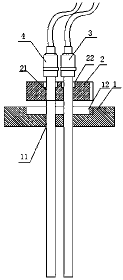
[0033] Such as figure 1 As shown, a thermocouple positioning device for thermal process equipment is used for installing thermocouples, including a chassis 1, the chassis 1 is installed on the thermal process equipment, and at least two test holes communicating with the interior of the thermal process equipment are provided on the chassis 1 11; and several positioning discs 2 with different heights, the corresponding test holes 11 on the positioning disc 2 are provided with at least two limit holes 21, the positioning disc 2 is detachably connected to the chassis 1; the thermocouple includes a test couple 3 and a calibration electrode The couple 4, the test couple 3 and the check couple 4 are inserted into the thermal process equipment through the limit hole 21 of the positioning plate 2 and the test hole 1...


PUM


Abstract

The invention discloses a thermocouple positioning device of thermal process equipment. The device comprises a chassis. The chassis is installed on the thermal process equipment, and the chassis is provided with at least two test holes communicated with the interior of the thermal process equipment; and a plurality of positioning discs with different heights, wherein the positioning discs are provided with at least two limiting holes corresponding to the test holes. The invention further discloses a precision verification method of the thermal process equipment, the test galvanic couple and the verification galvanic couple respectively and sequentially penetrate through the limiting hole of the positioning disc and the test hole of the chassis to be inserted into the thermal process equipment, and the insertion depth of the thermocouple is determined according to the positioning disc; and after the thermal process equipment is heated, the test data of the temperature measuring instrument, the verification galvanic couple and the test galvanic couple of the thermal process equipment are compared, and the precision verification of the temperature measuring system of the thermal process equipment and the precision verification method thereof are carried out.

Description

technical field [0001] The invention relates to the technical field of thermal process equipment control, in particular to a thermocouple positioning device for thermal process equipment and a precision checking method thereof. Background technique [0002] The system accuracy verification of thermal process equipment is to use a test system composed of test instruments and test sensors to verify the accuracy of the temperature reflected by the working system composed of working sensors and working instruments. System accuracy verification involves heat treatment, surface treatment, composite material bonding, hot forming, forging and casting, and almost all thermal process equipment, so it is widely used in thermal processing in the manufacturing industry. System accuracy verification is an important and indispensable technology. [0003] The current method of system accuracy verification is: when the verification period expires, stop production, arrange the test sensor ne...

Claims


Application Information

Patent Timeline
Patent Type & Authority Applications(China)
IPC IPC(8): G01K15/00G01K7/02G01K1/14
CPCG01K15/005G01K7/02G01K1/14
Inventor 陈波熊稚莉唐海燕
Owner CHENGDU AIRCRAFT INDUSTRY GROUP
Why Eureka
Try Eureka