
Method and system for solving oil reservoir reconstruction microseism monitoring fracture seismic source mechanism

A source mechanism and micro-seismic technology, applied in seismology, geophysical measurement, seismic signal recording, etc., can solve problems such as low calculation efficiency, high quality requirements, and high objective function requirements, and achieve high operation efficiency and noise resistance strong effect

Active Publication Date: 2020-05-19
CHINA PETROLEUM & CHEM CORP +1
View PDF8 Cites 6 Cited by
  • Summary
  • Abstract
  • Description
  • Claims
  • Application Information

AI Technical Summary

Problems solved by technology

At present, the conventional focal mechanism analysis method is to use the initial motion information of the longitudinal wave (P wave) to estimate the focal mechanism solution. The quality requirements are relatively high, and there are enough geophones to record the microseismic waveform, and the first arrival fluctuation signal with a high signal-to-noise ratio is required
In addition, solving the source mechanism based on the P-wave initial motion information of the microseismic signal has the disadvantages of low computational efficiency and high requirements for the objective function, and it is difficult to play a role in practical application

Method used


Image

  • Method and system for solving oil reservoir reconstruction microseism monitoring fracture seismic source mechanism
  • Method and system for solving oil reservoir reconstruction microseism monitoring fracture seismic source mechanism
  • Method and system for solving oil reservoir reconstruction microseism monitoring fracture seismic source mechanism

Examples


Embodiment Construction

[0026] In order to make the above and other objects, features and advantages of the present invention more comprehensible, the preferred embodiments are listed below and shown in the accompanying drawings in detail as follows.

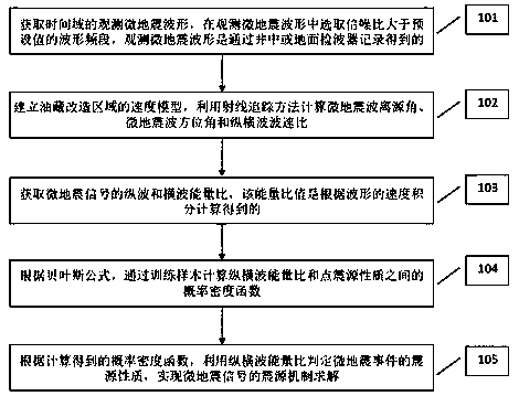
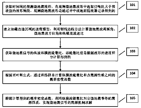
[0027] Such as figure 1 as shown, figure 1 It is a flow chart of the method for solving the microseismic focal mechanism of reservoir stimulation of the present invention.

[0028] In step 101, the observed micro-seismic waveform data in the time domain is obtained, and a waveform frequency band with a signal-to-noise ratio greater than a preset value is selected from the observed micro-seismic waveform.

[0029] The preset value of the signal-to-noise ratio is 3.0, that is, the focal mechanism is solved for microseismic waveform data with a signal-to-noise ratio greater than 3.0. The waveform frequency range is to analyze the signal-to-noise ratio of the microseismic waveform data in the time domain, select a frequency range greater than a preset va...


PUM


Abstract

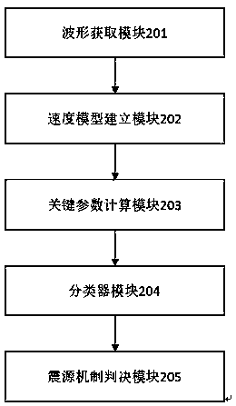
The invention provides a method and system for solving an oil reservoir reconstruction microseism monitoring fracture seismic source mechanism. The method comprises the following steps: step 1, obtaining observation microseism waveform data of a time domain; step 2, establishing a three-dimensional speed model of an oil reservoir transformation area; step 3, acquiring an energy ratio of longitudinal waves to transverse waves of microseism signals; step 4, according to a Bayesian formula, calculating a probability density function between a longitudinal wave and transverse wave energy ratio anda point seismic source property through a training sample; and step 5, according to the calculated probability density function, judging the seismic source property of a microseism event by utilizingthe longitudinal wave and transverse wave energy ratio, and solving the seismic source mechanism of the microseism event. According to the method and the system for solving the oil reservoir reconstruction microseism monitoring fracture source mechanism, whether an artificial fracture is a tensile fracture or a shear fracture can be determined through the method for solving the oil reservoir reconstruction microseism monitoring fracture source mechanism, so that the accurate characteristics of the artificial fracture are effectively described.

Description

technical field [0001] The invention relates to the technical field of microseismic monitoring for petroleum and natural gas reservoir reformation, in particular to a method and system for solving focal mechanism of cracks in microseismic monitoring for reservoir reformation. Background technique [0002] Reservoir stimulation operations such as hydraulic fracturing, water injection, gas injection, and heavy oil thermal recovery will induce microseismic events, and these microseismic activities play an important role in the exploration and development of various unconventional oil and gas fields. Extraordinary oil and gas resources have made great progress. Reservoir stimulation technologies such as hydraulic fracturing are inseparable from the support of related supporting technologies. Microseismic monitoring is one of the most effective technologies for evaluating reservoir stimulation effects and optimizing stimulation processes. At present, the conventional focal mechan...

Claims


Application Information

Patent Timeline
IPC IPC(8): G01V1/28G01V1/18G01V1/24
CPCG01V1/288G01V1/181G01V1/24G01V2210/1234
Inventor 刁瑞韩宏伟尚新民芮拥军张云银陈云峰崔庆辉
Owner CHINA PETROLEUM & CHEM CORP
Learn More