Eureka AIR delivers breakthrough ideas for toughest innovation challenges, trusted by R&D personnel around the world.

Optimization design method for composite material laminated plate layup

A composite material layer and optimization design technology, applied in computer-aided design, design optimization/simulation, calculation, etc., can solve problems such as not being able to fully join designers, changing the weight of the objective function, etc.

Pending Publication Date: 2020-05-19
DONGHUA UNIV
View PDF5 Cites 0 Cited by
  • Summary
  • Abstract
  • Description
  • Claims
  • Application Information

AI Technical Summary

Problems solved by technology

However, the existing multi-objective optimization methods for composite laminates, such as genetic algorithm, particle swarm algorithm, etc., take the ply thickness or ply angle as a separate design variable for optimal design, and the ply angle as a design variable , most of the optimization methods set the ply thickness as a fixed value, and there are few methods that consider the ply thickness and ply angle as variables at the same time
At the same time, the existing methods cannot fully add the designer's experience to change the weight of the objective function to achieve specific optimization purposes

Method used


Image

  • Optimization design method for composite material laminated plate layup
  • Optimization design method for composite material laminated plate layup
  • Optimization design method for composite material laminated plate layup

Examples


Embodiment Construction

[0044] Below in conjunction with specific embodiment, further illustrate the present invention. It should be understood that these examples are only used to illustrate the present invention and are not intended to limit the scope of the present invention. In addition, it should be understood that after reading the teachings of the present invention, those skilled in the art can make various changes or modifications to the present invention, and these equivalent forms also fall within the scope defined by the appended claims of the present application.

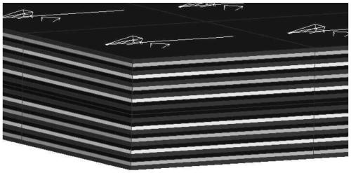
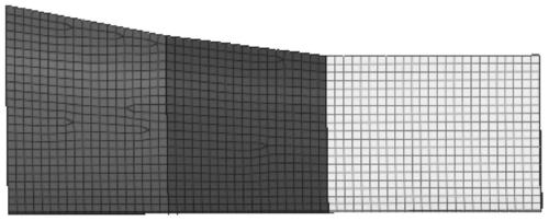
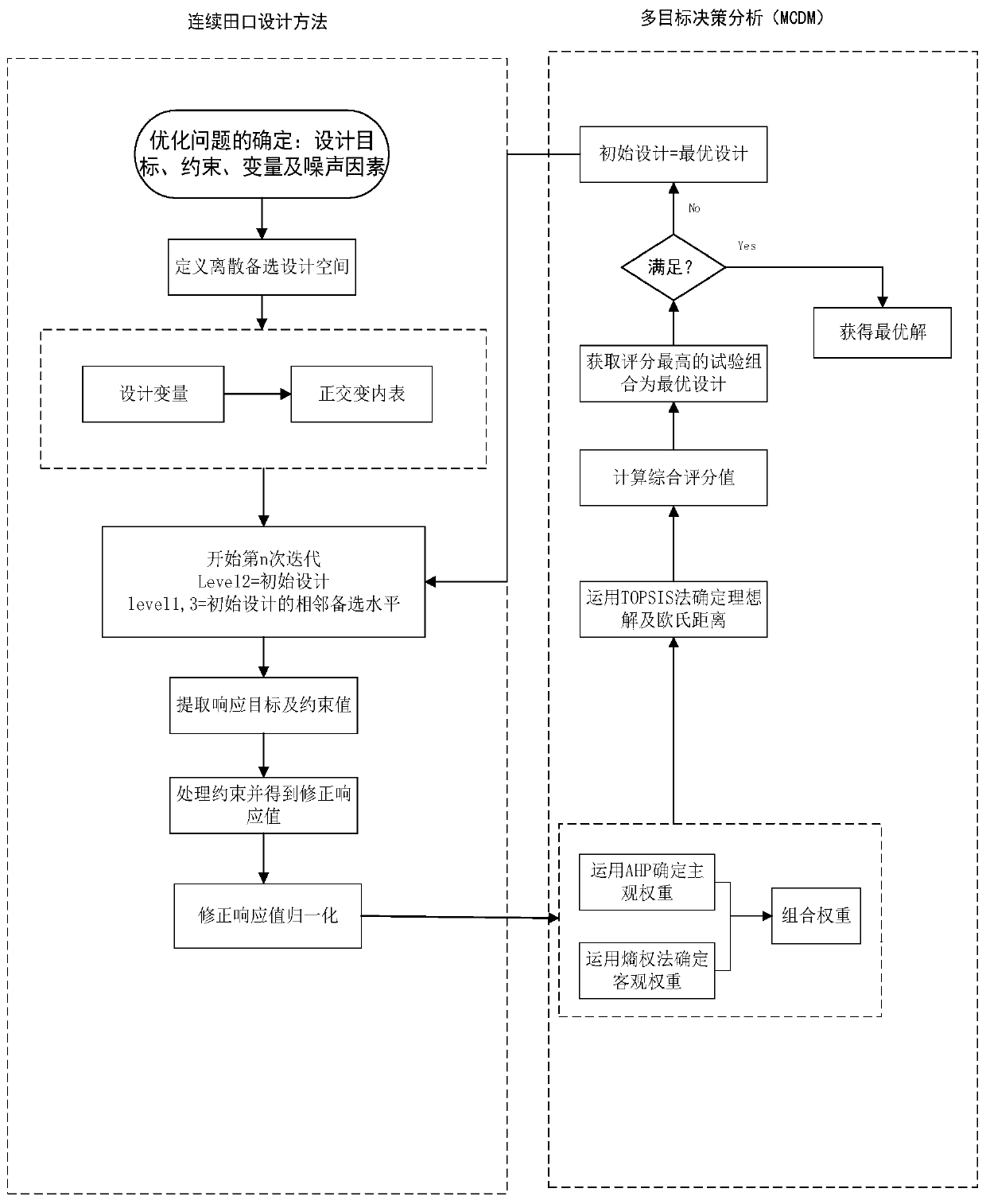
[0045] The embodiment of the present invention relates to a multi-objective optimization design method for a woven composite laminate layup; FIG. 1 shows a schematic diagram of a composite laminate layup, where red is 0°, green is 45°, and blue is 90°. Yellow is -45°; figure 2 is the composite material wing finite element model diagram; image 3 To optimize the design flow chart; the method specifically includes the followin...


PUM


Abstract

The invention relates to a multi-objective optimization design method for a composite laminated plate layup. The method specifically comprises the following steps: determining an objective function and constraints according to the working condition of a laminated plate; determining a layer number interval, and taking the layer number as a factor; selecting layering angles as levels, sorting the layering angles according to rules, and selecting three adjacent levels of factors to construct an orthogonal table; simulating according to orthogonal table scheme design, and extracting evaluation indexes in a result file; correcting a target response value by using a penalty function method; processing the corrected value by using a normalization method to obtain a decision matrix; determining subjective and objective weights of each index by using an analytic hierarchy process and an entropy weight method; combining the host or guest or combination weight with the decision matrix to obtain anew decision matrix; obtaining an optimal combination by using an approximate optimal solution sorting method; and constructing an orthogonal table by taking the level of the optimal combination as areference, and continuing iteration until conditions are met. The method can solve the problem that the number of layers of the composite material changes, and is small in iteration frequency.

Description

technical field [0001] The invention relates to the field of composite material part design, in particular to a multi-objective optimization design method for composite material laminated board layers. Background technique [0002] Composite laminates are widely used in aerospace, ships, automobiles and other fields due to their low density, high specific strength, high specific stiffness and designability of mechanical properties. The mechanical properties of the laminate are closely related to the thickness of the ply and the angle of each ply. Therefore, optimizing the thickness of the ply and the angle of the ply are two important ways to improve the mechanical properties of the laminate, and the laminate is often under various working conditions. Bearing multiple loads is a multi-objective optimization problem. However, the existing multi-objective optimization methods for composite laminates, such as genetic algorithm, particle swarm algorithm, etc., take the ply thic...

Claims


Application Information

Patent Timeline
Patent Type & Authority Applications(China)
IPC IPC(8): G06F30/20G06F113/26
Inventor 孔永华周衡单立军陆云韬
Owner DONGHUA UNIV
Why Eureka
Eureka Blog
Learn More