Intelligent beverage vending machine and method thereof
A technology for vending machines and beverages, which is applied in the direction of coin-operated equipment, instruments, coinless or similar appliances for distributing discrete items, which can solve the problems of high maintenance costs, low efficiency, and complex structures, and achieve low maintenance costs , comprehensive functions and simple structure
- Summary
- Abstract
- Description
- Claims
- Application Information
AI Technical Summary
Problems solved by technology
Method used
Image

Examples
Embodiment 1
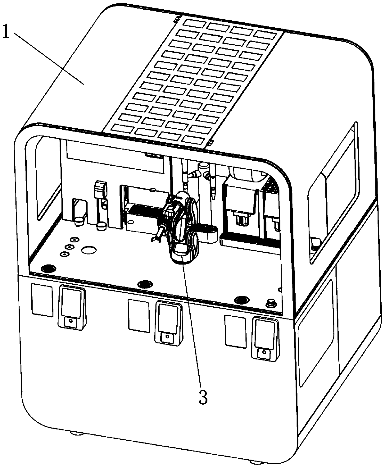
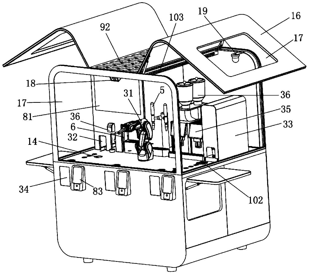
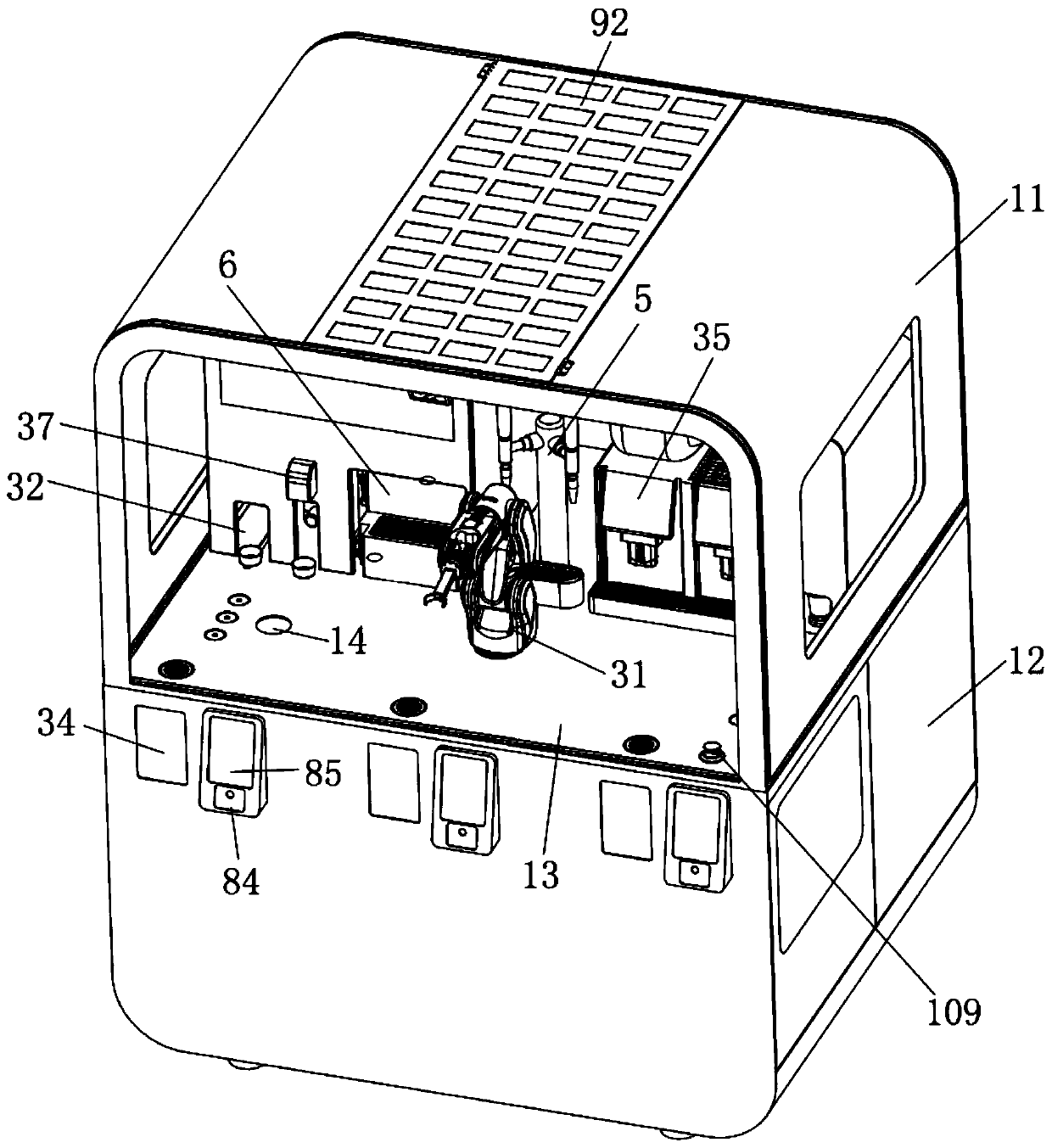
[0065] refer to Figure 1 to Figure 5 , an intelligent beverage vending machine, comprising: a vending machine cabinet 1 and a beverage output assembly 3 arranged in the vending machine cabinet 1, wherein the beverage output assembly 3 includes: a mechanical arm gripper 31 for moving the position of the beverage container And the cup drop mechanism 32 for storing the beverage container arranged around the gripper 31 of the mechanical arm, the cup cover mechanism 33 for sealing the beverage container, the beverage machine 35 for adding finished beverage to the beverage container, A material mechanism 36 for adding semi-finished materials to the beverage container and a meal delivery mechanism 34 for outputting finished beverages.
[0066] In another embodiment, the vending machine cabinet 1 is composed of an upper cabinet 11, a lower cabinet 12, and a component mounting plate 13 arranged between the upper cabinet 11 and the lower cabinet 12, and the upper cabinet 11 cooperates ...
Embodiment 2
[0108] see Figure 8-Figure 10 , the difference from the above-mentioned embodiment is that the gripper 31 of the robotic arm includes: a gripper 311 for gripping an article, a gripper 313 for controlling the gripper 311 and a gripper 311 for connecting the gripper 311 and the gripper 313 The clamping jaw fixture 312, wherein the clamping jaw 311 includes: a clamping jaw finger 3111 for gripping an article and a sensor 314 arranged at the joint between the clamping jaw finger 3111 and the clamping jaw fixing member 312, and the sensor 314 is used to detect the clamping jaw finger 3111 Whether the clamping object is clamped in place.
[0109] Preferably, the side of the gripper finger 3111 close to the object to be picked is arranged in an arc shape, and the side connected to the gripper fixture 312 is provided with a connection surface 3113 . By setting the side of the gripper finger 3111 close to the gripping object to be arc-shaped, the design of the cup body in the prior a...
Embodiment 3
[0123] refer to Figure 8 and Figure 11 The difference from Embodiment 1 is that the mechanical arm 313 includes: a rotating arm 3131 fixed at any position, a connecting arm 3132 / 3133 connected to the rotating arm 3131, and an end of the connecting arm 3132 / 3133 away from the rotating arm 3131 The clamping control arm 3134 of the clamping jaw fixture 312 is connected to the clamping control arm 3134 .
[0124] Preferably, the rotating arm 3131 is arranged on the base 3134, and the base 3134 can be fixed at any position, and a horizontal rotating member 3135 is provided between the rotating arm 3131 and the base 3134, so that the rotating arm can move in the horizontal direction To rotate, the end of the rotating arm 3131 away from the base 3134 is used to connect with the connecting arm.
[0125] Further preferably, a connecting arm rotating member 3136 is provided at the joint between the rotating arm 3131 and the connecting arm, and the connecting arm rotating member 3136...
PUM
 Abstract
Description
Claims
Application Information
 - R&D Engineer
- R&D Manager
- IP Professional
- Industry Leading Data Capabilities
- Powerful AI technology
- Patent DNA Extraction
Browse by: Latest US Patents, China's latest patents, Technical Efficacy Thesaurus, Application Domain, Technology Topic.
© 2024 PatSnap. All rights reserved.Legal|Privacy policy|Modern Slavery Act Transparency Statement|Sitemap