Supercharge Your Innovation With Domain-Expert AI Agents!

Arc extinguishing device of circuit breaker

A technology of arc extinguishing device and circuit breaker, which is applied in the direction of high-voltage air circuit breakers, circuits, electrical components, etc., can solve the problems of high-position loss of magnetism of permanent magnets, and achieve the effect of meeting the requirements of non-polarity, simple assembly, and simple structure

Pending Publication Date: 2020-05-19
SHANGHAI LIANGXIN ELECTRICAL
View PDF0 Cites 0 Cited by
  • Summary
  • Abstract
  • Description
  • Claims
  • Application Information

AI Technical Summary

Problems solved by technology

[0004] The purpose of the present invention is to provide an arc extinguishing device for a circuit breaker, which improves the efficiency of the circuit breaker in breaking small currents, in view of the technical defect that the permanent magnet is used to draw the arc in the arc extinguishing chamber of the above-mentioned DC circuit breaker, and the permanent magnet is easily subjected to high-level demagnetization. Reliability, and meet the arc extinguishing requirements of non-polarity circuit breakers

Method used


Image

  • Arc extinguishing device of circuit breaker
  • Arc extinguishing device of circuit breaker
  • Arc extinguishing device of circuit breaker

Examples


Embodiment 1

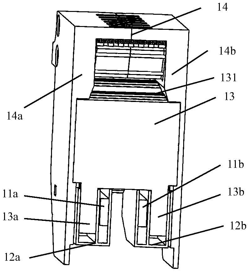
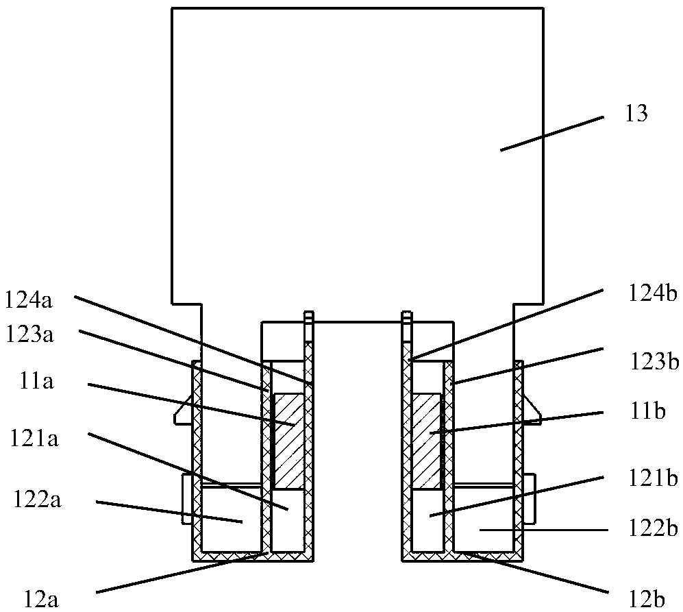
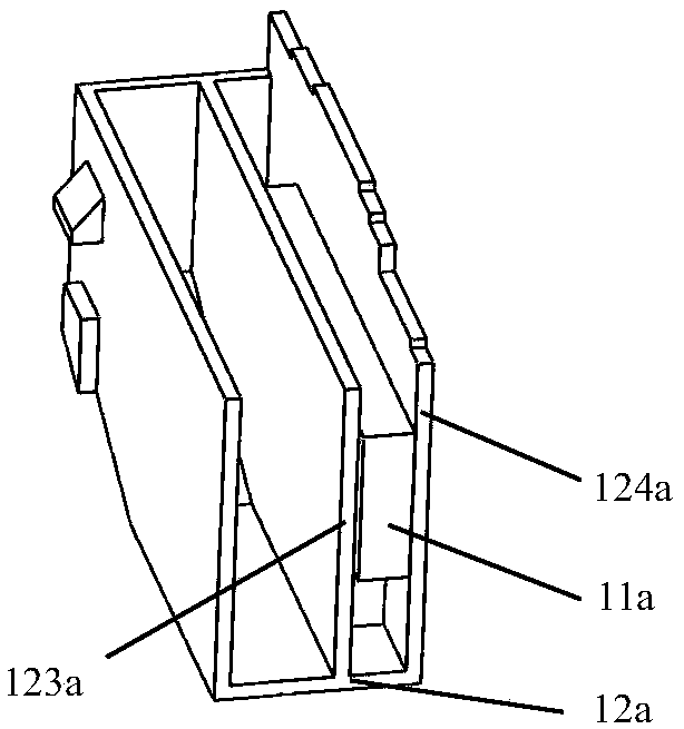
[0025] as attached figure 1 with 2 The illustrated embodiment provides an arc extinguishing device for a circuit breaker, which includes a housing 14, the housing 14 includes a left partition 14a and a right partition 14b, and the left partition 14a and the right partition 14b are made of insulating materials production. The arc extinguishing grid group 131 is placed in the semi-closed chamber in the housing 14, and the arc extinguishing grid group 131 includes several parallel arc extinguishing grids 13, and the arc extinguishing grids 13 are made of magnetic materials . The arc extinguishing grid set 131 protrudes a pair of grid legs 13a, 13b toward the mouth of the housing 14. In this embodiment, the pair of grid legs 13a, 13b are U-shaped or V-shaped. shape. The pair of grid legs 13a, 13b are installed in the corresponding compartments 122a, 122b on the corresponding pair of gas production covers 12a, 12b, wherein, the pair of gas production covers 12a, 12b are also pr...

Embodiment 2

[0029] as attached Figure 5 As shown, the present invention also provides a circuit breaker arc extinguishing device, the pair of grid legs 13a, 13b protruding from the arc extinguishing grid set 131 are not installed in the pair of gas production covers 12a, 12b , the pair of gas production covers 12a, 12b are arranged on the left and right sides of the arc extinguishing grid set 131 on the mouth side of the housing 14, and the pair of permanent magnets 11a, 11b are mounted on the pair of production The third compartment 125a, 125b of the gas shield 12a, 12b is isolated from the arc generation area of ​​the arc extinguishing device, and other structures and principles are the same as those of the first embodiment.

Embodiment 3

[0031] as attached Image 6 As shown, the present invention also provides a circuit breaker arc extinguishing device, the arc extinguishing grid group 131 is not provided with a pair of grid legs, and the pair of gas production covers 12a, 12b are arranged on the arc extinguishing grid The sheet group 131 is located on the left and right sides of the mouth of the housing 14, and a pair of permanent magnets 11a, 11b are installed in the third compartments 125a, 125b of the pair of gas generating hoods 12a, 12b to generate arcs with the arc extinguishing device. Area isolation, other structures and principles are the same as those in Embodiment 1.


PUM


Abstract

The invention discloses an arc extinguishing device of a circuit breaker. The device comprises a shell (14), and the arc extinguishing grid sheet group (131) is arranged in the shell (14); the arc extinguishing grid sheet group (131) extends out of a pair of grid sheet legs (13a, 13b) towards the opening part of the shell (14); the pair of grid sheet legs (13a, 13b) are arranged in the compartments I (122a, 122b) on the corresponding pair of gas production hoods (12a, 12b); the arc extinguishing device is characterized in that the pair of gas generating hoods (12a, 12b) are also provided withcompartments II (121a, 121b), and the pair of permanent magnets (11a, 11b) are arranged in the corresponding compartments II (121a, 121b). The whole arc extinguishing device is simple in structure andeasy to assemble, and can effectively and quickly blow small critical current into the arc extinguishing chamber to achieve the purpose of quick arc extinguishing. The permanent magnet generates electromagnetic force to blow the arc to the arc extinguishing chamber, the electromagnetic force can be generated in the forward and reverse directions of the current, and the non-polarity requirement ofthe product is met.

Description

technical field [0001] The invention belongs to the technical field of circuit breakers, and in particular relates to an arc extinguishing device for a circuit breaker. Background technique [0002] Circuit breakers are an important part of power distribution appliances. They are mainly used in industrial low-voltage power systems to connect and break currents in grid circuits and protect lines and power supply equipment from overload, undervoltage, short circuit, single-phase grounding, etc. hazard of failure. The function of the circuit breaker to break the overload or short-circuit current is mainly completed by the arc extinguishing chamber installed in the circuit breaker. When a fault current occurs in the circuit and the current value exceeds the set protection range of the circuit breaker, the tripping mechanism operates to quickly disconnect the dynamic and static contacts of the circuit breaker. At this time, the voltage between the dynamic and static contacts cau...

Claims


Application Information

Patent Timeline
IPC IPC(8): H01H33/08H01H33/18
CPCH01H33/08H01H33/182
Inventor 张广智李惠敏朱沈锋
Owner SHANGHAI LIANGXIN ELECTRICAL
Features
  • R&D
  • Intellectual Property
  • Life Sciences
  • Materials
  • Tech Scout
  • Unparalleled Data Quality
  • Higher Quality Content
  • 60% Fewer Hallucinations
Learn More