
Connection method of energy storage battery and UPS and charging and discharging control method

A charging and discharging control, energy storage battery technology, applied in electrical components, circuit devices, emergency power supply arrangements, etc., can solve problems such as the inability to guarantee backup power supply, and achieve the effect of avoiding floating charging and improving reliability.

Active Publication Date: 2020-05-19
宁波中科孚奇能源科技有限公司
View PDF8 Cites 1 Cited by
  • Summary
  • Abstract
  • Description
  • Claims
  • Application Information

AI Technical Summary

Problems solved by technology

[0006] The addition of new energy storage batteries in the above method does not solve the problem of long-term floating charging of the original lead-acid batteries, and there are always potential safety hazards; The access of the energy battery needs switching time. If the original lead-acid battery fails at this time, the new energy storage battery cannot guarantee the backup power supply in time.

Method used


Image

  • Connection method of energy storage battery and UPS and charging and discharging control method
  • Connection method of energy storage battery and UPS and charging and discharging control method
  • Connection method of energy storage battery and UPS and charging and discharging control method

Examples


Embodiment 1

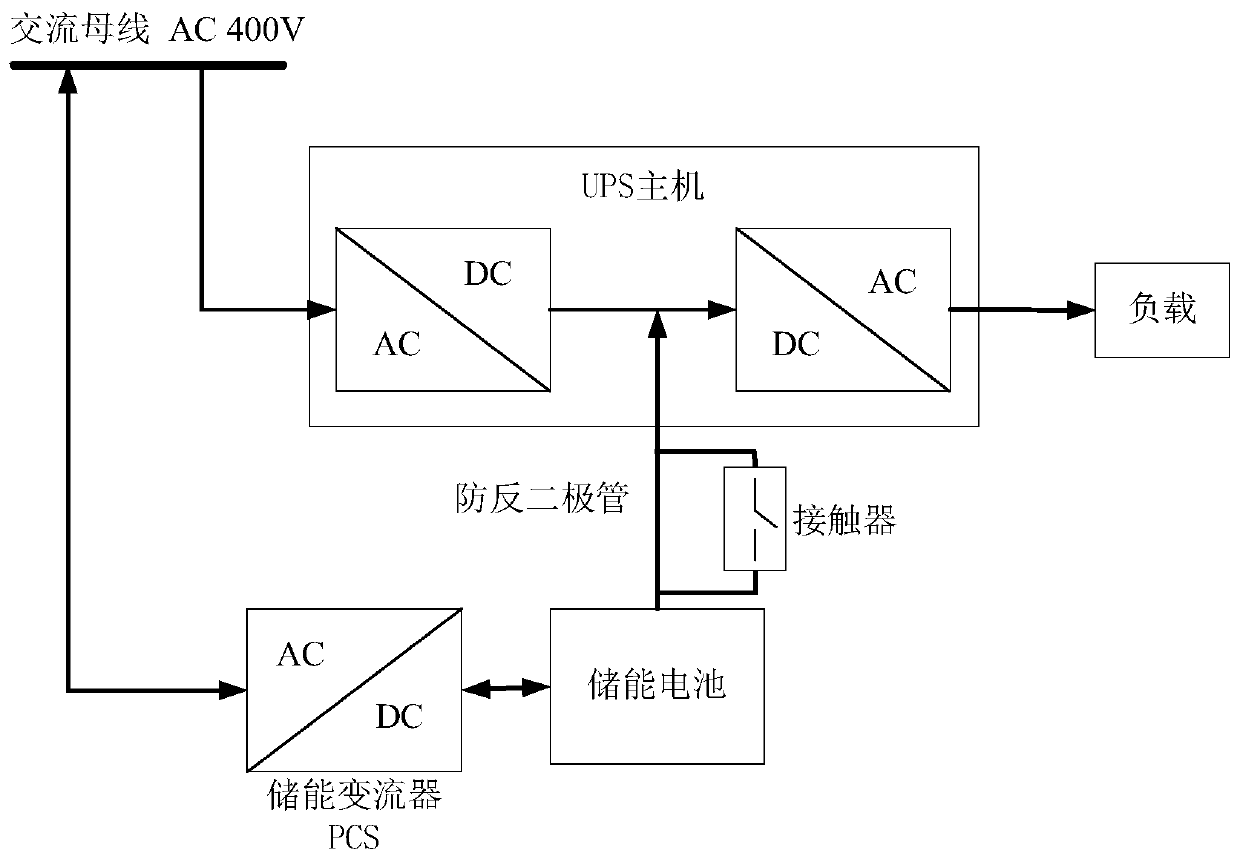
[0048] The connection method between the energy storage battery and the UPS is as follows: figure 2 As shown, the UPS includes a UPS host, an energy storage battery, an AC load, and a utility power. Wherein, the UPS host includes a power supply device for converting commercial power into direct current and a power supply device for converting direct current into commercial power. The energy storage battery is connected to the PCS, and the mutual conversion between the energy storage battery and the mains is realized through the PCS. The energy storage battery is connected to the UPS host through the anti-reverse diode, and the anti-reverse diode is connected in parallel with the contactor. The anti-reverse diode is used to prevent the UPS host from charging the energy storage battery. The contactor is connected, and the UPS host charges the energy storage battery. The energy storage battery can supply power to the load in time when the mains power is cut off.

[0049] Aft...

Embodiment 2

[0055] In this embodiment, the connection method between the energy storage battery and the UPS is the same as that in Embodiment 1.

[0056] After the above energy storage battery is connected to UPS, if Figure 4 As shown, the PCS and contactor are controlled by the monitoring device. The specific control method is as follows Figure 6 shown, including the following steps:

[0057] (1) The monitoring device sets the target backup capacity and charging power threshold, the target backup capacity is 80% of the total capacity of the energy storage battery, and the charging power threshold is 10% of the total power of the UPS;

[0058] (2) The energy storage battery includes a battery management system (BMS), and the BMS monitors the power of the energy storage battery; when the power is equal to the total capacity of the energy storage battery, the battery is fully charged, and the following step (3) is performed; otherwise, the battery is not fully charged, and the Following...

Embodiment 3

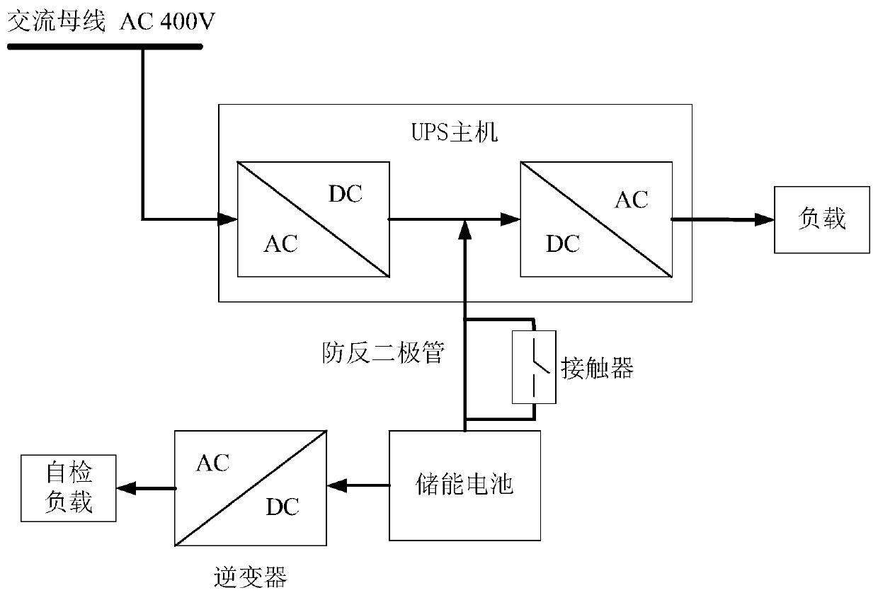
[0062] The connection method between the energy storage battery and the UPS is as follows: image 3 As shown, the UPS includes a UPS host, an energy storage battery, an AC load, and a utility power. Wherein, the UPS host includes a power supply device for converting commercial power into direct current and a power supply device for converting direct current into commercial power. The energy storage battery is connected to the load through the inverter. The energy storage battery is connected to the UPS host through the anti-reverse diode, and the anti-reverse diode is connected in parallel with the contactor. The anti-reverse diode is used to prevent the UPS host from charging the energy storage battery. The contactor is connected, and the UPS host charges the energy storage battery. The energy storage battery can supply power to the load in time when the mains power is cut off.

[0063] After the above energy storage battery is connected to UPS, if Figure 7 As shown, th...


PUM


Abstract

The invention provides a connection method of an energy storage battery and a UPS, the energy storage battery is used for replacing a lead-acid battery, the energy storage battery is connected with aPCS or an inverter, the energy storage battery is connected with a UPS host through an anti-reverse diode, and the anti-reverse diode is connected with a contactor in parallel. According to the connection method, the UPS host does not need to be modified, and timely power supply of the energy storage battery can be realized under the condition of mains supply outage. Moreover, the invention provides a charging and discharging method of the energy storage battery. The PCS, the inverter and the contactor are controlled through the monitoring device; the target backup capacity is set, under the control of the monitoring device, the electric quantity of the energy storage battery always reaches the target standby capacity; the difference between the total capacity of the energy storage batteryand the target standby capacity is used as the automatic charging and discharging capacity to automatically charge the energy storage battery and automatically discharge the PCS or the inverter, floating charge of the battery can be avoided, and the actual state of the energy storage battery can be monitored through PCS or inverter discharge, so that the reliability of the energy storage batteryis improved.

Description

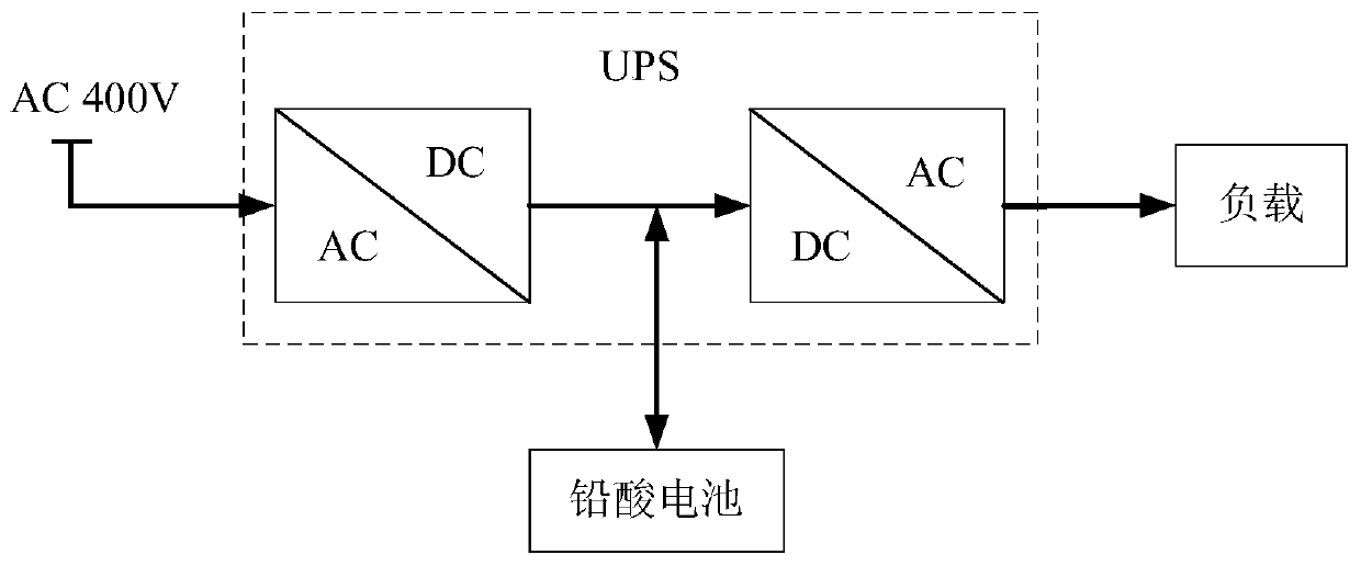
technical field [0001] The invention belongs to power electronics technology, and in particular relates to a method for connecting an energy storage battery to a UPS and a method for controlling charging and discharging. Background technique [0002] UPS (Uninterruptible Power Supply), that is, uninterruptible power supply, is a system device that connects batteries (mostly lead-acid maintenance-free batteries) with electronic circuits, and converts direct current into commercial power through modular circuits such as inverters. It is mainly used for Providing stable and uninterrupted power supply for computers, computer network systems or other power electronic equipment, such as solenoid valves and pressure transmitters, is the cornerstone of ensuring information security and industrial automation. When the mains input is normal, the UPS will stabilize the mains and supply it to the load. At this time, the UPS is an AC voltage stabilizer, and it also charges the battery in...

Claims


Application Information

Patent Timeline
Patent Type & Authority Applications(China)
IPC IPC(8): H02J9/06H02J3/32
CPCH02J9/061H02J3/32Y04S20/20Y02B70/30
Inventor 田中和郑达邹印龙严加斌
Owner 宁波中科孚奇能源科技有限公司
Learn More