
Wide-output-gain multi-resonant-cavity LLC resonant converter

A resonant converter and resonant cavity technology, applied in the direction of output power conversion device, DC power input conversion to DC power output, instruments, etc., can solve the problems of increasing switching loss, increasing circuit cost, low work efficiency, etc., to achieve increased Great work efficiency, work efficiency improvement, the effect of improving work efficiency

Inactive Publication Date: 2020-05-19
ZHEJIANG UNIV
View PDF1 Cites 4 Cited by
  • Summary
  • Abstract
  • Description
  • Claims
  • Application Information

AI Technical Summary

Problems solved by technology

[0006] The LLC resonant converter, because of the PWM control strategy, has the problem of high circulating current in the circuit and low working efficiency
At the same time, the additional high-frequency working switch tube not only increases the switching loss, but also increases the circuit cost

Method used


Image

  • Wide-output-gain multi-resonant-cavity LLC resonant converter
  • Wide-output-gain multi-resonant-cavity LLC resonant converter
  • Wide-output-gain multi-resonant-cavity LLC resonant converter

Examples


Embodiment Construction

[0045] The present invention will be further described below in conjunction with the accompanying drawings and specific embodiments. It should be understood that these examples are only used to illustrate the present invention and are not intended to limit the scope of the present invention. For the experimental methods without specific conditions indicated in the following examples, the conventional conditions or the conditions suggested by the manufacturer are usually followed.

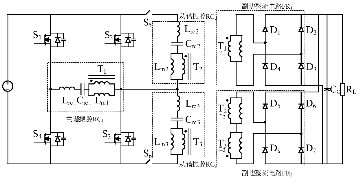
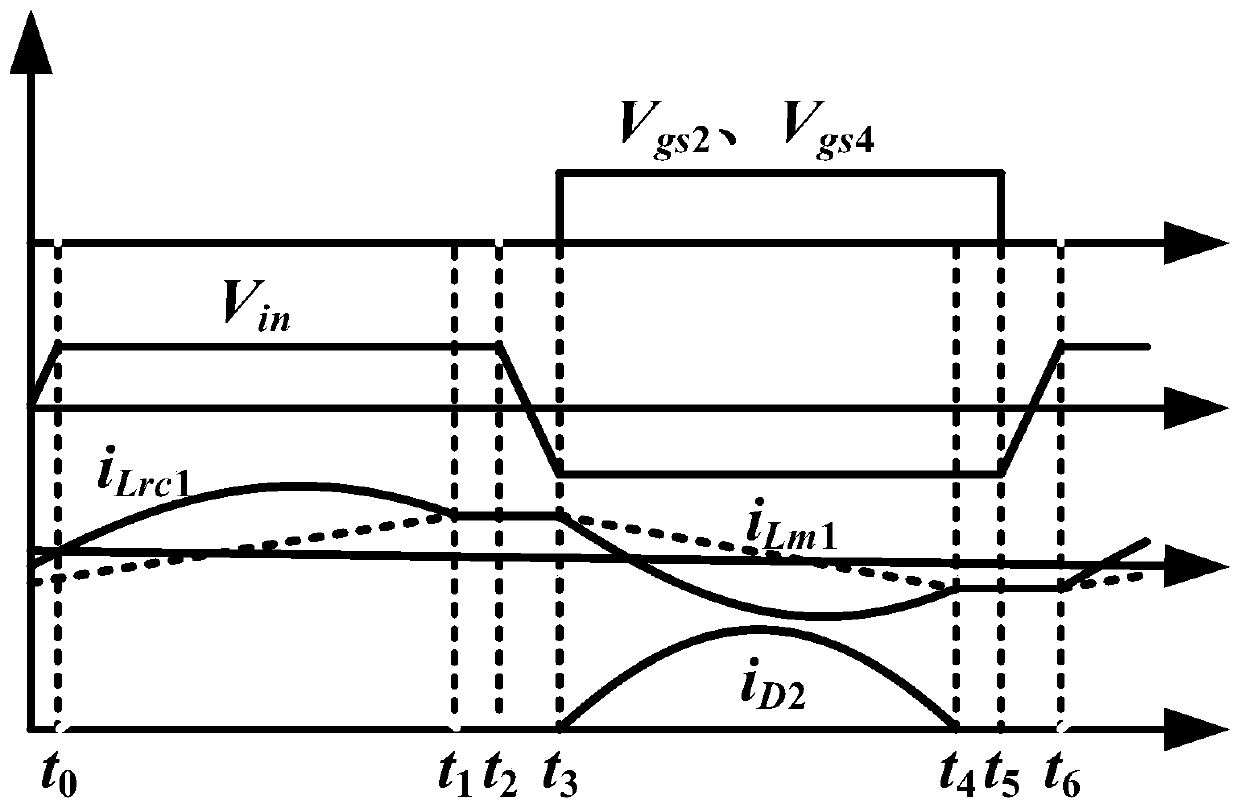
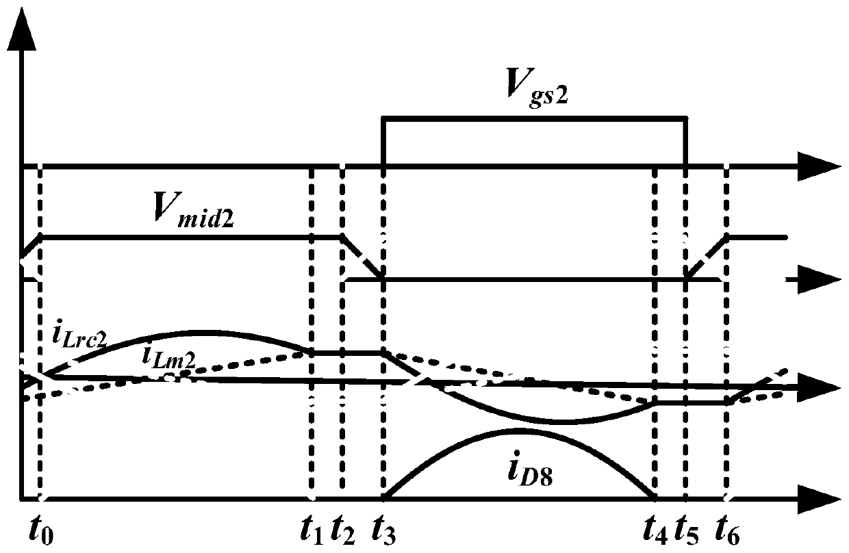
[0046] Such as figure 1 As shown, the multi-resonator LLC resonant converter of this embodiment includes a primary switch network with four switch tubes S 1 , S 2 , S 3 , S 4 . The main resonant cavity includes the main resonant cavity resonant inductance L rc1 , resonant capacitor C rc1 , Transformer T 1 and its primary magnetizing inductance L m1 . One end of the resonant inductor is connected to the midpoint of the bridge arm of the leading bridge arm, and the other end is connected to ...


PUM


Abstract

The invention discloses a multi-resonant-cavity LLC resonant converter, which comprises a primary side switching network, a main resonant cavity RC1, auxiliary resonant cavities RC2 and RC3, auxiliaryresonant cavity switched-in switched-out switching tubes S5 and S6, a corresponding rectifying circuit FR1 when the main resonant cavity RC1 works, and a corresponding rectifying circuit FR2 when theauxiliary resonant cavities RC2 and RC3 work. According to the invention, the circuit can be in different working modes, i.e., a high-voltage output working mode, a medium-voltage output working modeand a low-voltage output working mode, by switching the resonant cavities in which the circuit actually works, and the gain ranges in the three working modes are continuous, so that the circuit obtains a wide output gain; and meanwhile, under the three working modes, the circuit can achieve the required output gain in a rated working frequency range by adopting a frequency conversion control mode, so that soft switching of the switching tubes in a full output gain range is ensured, relatively large ring current is avoided, and relatively high working efficiency of the circuit in the full output gain range is ensured.

Description

technical field [0001] The invention relates to the technical field of power electronic converters, in particular to a wide output gain multi-resonant cavity LLC resonant converter. Background technique [0002] At present, with the development of science and technology, the high frequency of power electronic devices has become an important development direction in electronic electronics. However, increasing the frequency of power electronic converters has a problem of increasing switching losses. For this problem, soft switching technology came into being, which can eliminate the switching loss of the circuit by turning on the switching tube with zero voltage. The LLC resonant converter has excellent soft switching characteristics and electromagnetic compatibility characteristics. However, the output gain of the LLC resonant converter is limited in the frequency conversion mode, and it is difficult to meet the demand for wide output gain in practical applications. Theref...

Claims


Application Information

Patent Timeline
Patent Type & Authority Applications(China)
IPC IPC(8): H02M3/335
CPCH02M3/33569H02M1/0058Y02B70/10
Inventor 马皓周嘉轩
Owner ZHEJIANG UNIV
Learn More