
Demagnetization control device of brushless DC motor and implementation method thereof

A brush DC motor and control device technology, applied in the direction of electronically commutated motor control, control systems, electrical components, etc., can solve the problems of inability to absorb potential energy, inability to be released, inability to conduct electricity normally in the conduction phase, etc., to achieve The effect of simple structure, elimination of interference and low cost

Active Publication Date: 2020-05-19
JIANGSU UNIV OF SCI & TECH
View PDF6 Cites 0 Cited by
  • Summary
  • Abstract
  • Description
  • Claims
  • Application Information

AI Technical Summary

Problems solved by technology

From the method point of view, it is very perfect, but the absorbing circuit can not effectively absorb the potential energy generated by the self-inductance phenomenon of the off-phase at all, and the capacitor after energy storage in the absorbing circuit cannot be controlled through control. If it is released, and if the IGBT tube that controls the energy storage of the capacitor in its absorbing circuit has a freewheeling diode, it will cause the conduction phase to be equivalent to a load composed of a resistor and a capacitor connected in parallel, so that the conduction phase cannot be energized normally
And after investigation, in the prior art, there is no circuit that is effectively connected in parallel to the three-phase windings of the brushless DC motor to absorb the potential energy generated by the self-inductance phenomenon after the relevant break.

Method used


Image

  • Demagnetization control device of brushless DC motor and implementation method thereof
  • Demagnetization control device of brushless DC motor and implementation method thereof
  • Demagnetization control device of brushless DC motor and implementation method thereof

Examples


Embodiment Construction

[0025] The present invention will be described in detail in conjunction with accompanying drawing now.

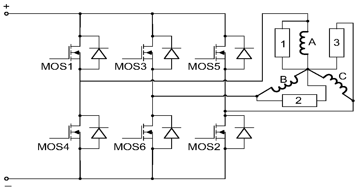
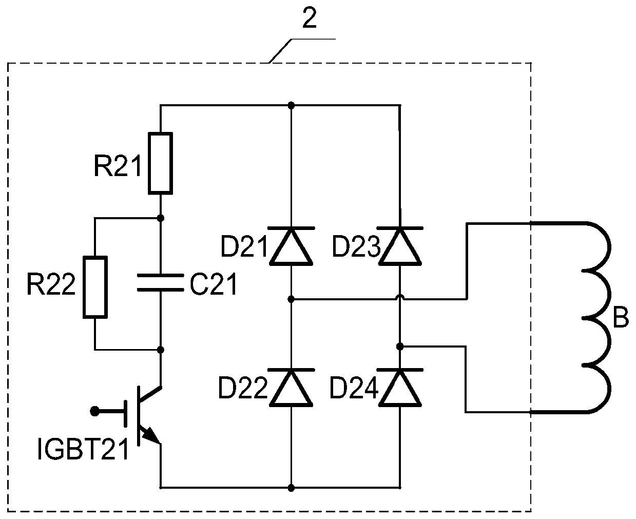
[0026] Such as figure 1 As shown, a degaussing control device for a brushless DC motor of the present invention includes an inverter, a three-phase armature winding of a motor, a first absorbing circuit (1), a second absorbing circuit (2) and a third absorbing circuit (3 ); wherein, the inverter is sequentially connected by 3 pairs of MOS tube bridge arms, and the output of the inverter is connected to the three-phase armature winding of the motor; the first absorption circuit (1) is in phase with the A-phase winding In parallel connection, the second absorbing circuit (2) is connected in parallel with the B-phase winding; the third absorbing circuit (3) is connected in parallel with the C-phase winding; the A-phase winding, the B-phase winding and the C-phase winding are star-connected.

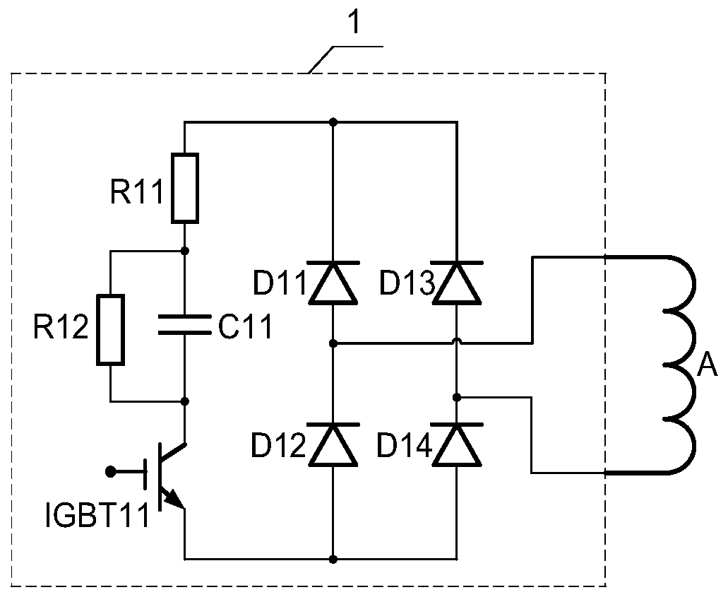
[0027] Such as figure 2 As shown, specifically, the first absorption circuit (1) i...


PUM


Abstract

The invention discloses a demagnetization control device of a brushless DC motor and an implementation method thereof. The device is characterized in that absorption circuits in the control device are connected with three phases of armature windings in parallel respectively, and are respectively provided with a full-bridge rectification circuit; the input of each full-bridge rectification circuitis connected to the two ends of the corresponding phase respectively; and the outputs of the full-bridge rectification circuits are connected to specific energy consumption absorption and energy storage circuits composed of IGBTs, resistors and capacitors. In the phase change period of the motor, the absorption circuit connected to the non-conducted phase in the three phases of the armature windings effectively works, so that the phase change reliability of the sensorless brushless DC motor is effectively improved, and the interference of the self-inductance effect of the armature windings oncounter potential zero-crossing detection is effectively eliminated; and the capacitor with stored electric energy in the absorption circuit is naturally released after the IGBT is closed.

Description

technical field [0001] The invention relates to the field of sensorless brushless DC motor phase commutation, in particular to a brushless DC motor degaussing control device and an implementation method thereof. Background technique [0002] Brushless DC motor has good linear speed regulation, high quality, high efficiency and smooth running characteristics, simple structure, small size, light weight, high efficiency, high power factor, high torque / weight ratio, low moment of inertia, easy heat dissipation, easy maintenance Maintenance and other advantages, so the scope of application is quite wide. With the rapid development of power electronic devices, brushless DC motors use electronic commutation devices to replace mechanical brushes and commutators, which greatly improves the production efficiency and quality of industrial manufacturing and related automated power system departments. Cost and operational reliability, brushless DC motor position sensorless control has b...

Claims


Application Information

Patent Timeline
Patent Type & Authority Applications(China)
IPC IPC(8): H02P6/182
CPCH02P6/182
Inventor 程蕤涵冯晓钰张静程科王长宝
Owner JIANGSU UNIV OF SCI & TECH
Learn More