
Vibration control method of sensorless permanent magnet synchronous motor

A permanent magnet synchronous motor and sensor technology, which is applied in motor control, motor generator control, AC motor control, etc., can solve the problems of signal-to-noise ratio reduction, inability to be filtered out by filters, high-frequency harmonic component position deviation information, etc. , to suppress the influence of motor vibration and noise, improve acoustic stealth ability, and be easy to realize in engineering

Active Publication Date: 2020-05-19
WUHAN MARINE ELECTRIC PROPULSION RES INST CHINA SHIPBUILDING IND CORP NO 712 INST
View PDF5 Cites 3 Cited by
  • Summary
  • Abstract
  • Description
  • Claims
  • Application Information

AI Technical Summary

Problems solved by technology

[0005] (1) The frequency of high-frequency injection signals is usually set at 200-500Hz, which is in the sensitive area of ​​human ears, and the high-frequency harmonic components contain position deviation information, which cannot be filtered out by filters;
[0006] (2) Reducing the amplitude of the injected signal can reduce the amplitude of the high-frequency current, but due to the influence of non-ideal characteristics such as the dead zone of the inverter, the position signal-to-noise ratio is also reduced;
[0007] (3) Increasing the frequency of the injected signal can also reduce the amplitude of the high-frequency current, but it will also bring about the problem of reducing the signal-to-noise ratio, and limited by the switching frequency and sampling law, the frequency of the injected signal cannot be increased without limit

Method used


Image

  • Vibration control method of sensorless permanent magnet synchronous motor
  • Vibration control method of sensorless permanent magnet synchronous motor
  • Vibration control method of sensorless permanent magnet synchronous motor

Examples


Embodiment 1

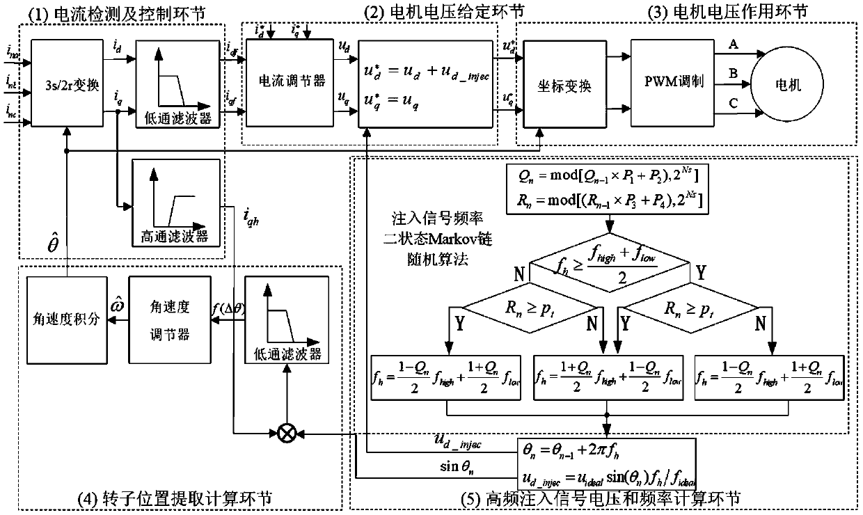
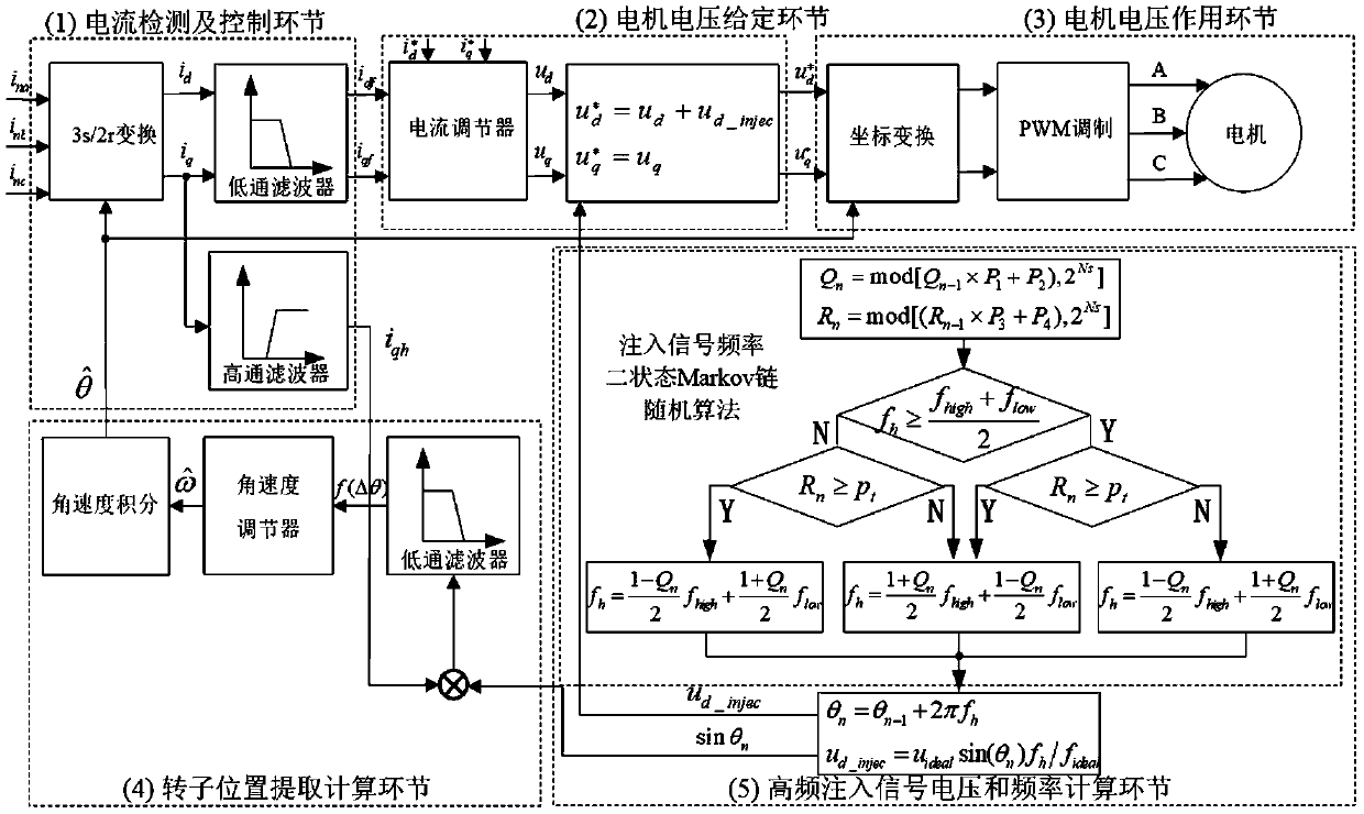
[0041] Such as figure 1 As shown, the present invention is used for a three-phase or 3N-phase permanent magnet propulsion synchronous motor powered by a voltage-type inverter. The calculation link 4 is composed of the high-frequency injection signal voltage and frequency calculation link 5.

[0042] The control method includes the following steps:

[0043] Step 1. Obtain the three-phase current i of the permanent magnet synchronous motor through the sampling of the AC current sensor na i nb and i nc , and then identify the angle according to the rotor position Use the 3s / 2r transformation of the rotating coordinate system to obtain i that contains DC components and high-frequency AC components d and i q , where i d and i q The DC component in the current is used for air gap flux linkage vector control, and the AC component is used for rotor position identification, including:

[0044] Step 1.1, the current i in the stationary three-phase coordinate system na i nb a...

Embodiment 2

[0064] A salient-pole three-phase permanent magnet synchronous motor is taken as an example to illustrate the implementation of the control method. The rated power of the motor is 87kW, the rated line voltage is 268V, the rated current is 201.5A, the rated speed is 810r / min, the number of pole pairs is 5, the stator resistance is 0.1Ω, the quadrature axis inductance is 367.5μH, the direct axis inductance is 285μH, and the salient pole ratio is 1.28.

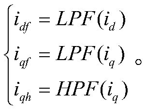
[0065] Step 1. Obtain the three-phase current i of the permanent magnet synchronous motor through the sampling of the AC current sensor na i nb and i nc , using the position to identify the angle According to the transformation of the rotating coordinate system, the orthogonal and direct axis current i is obtained d and i q ; The cutoff frequencies of the low-order and high-order filters are both set to 5Hz, and the AC-D axis DC components for vector control are obtained.

[0066] Step 2, calculate the given motor voltage i...


PUM


Abstract

The invention discloses a vibration control method of a sensorless permanent magnet synchronous motor. Firstly, a certain three-phase current of the permanent magnet synchronous motor is sampled; according to rotor position coordinate transformation, a current containing a DC component and a high-frequency AC component is obtained; a given motor voltage is calculated under a rotating coordinate system; then, by utilizing static coordinate system transformation and a space vector pulse width modulation SVPWM technology, the given voltage acts on each phase winding of the permanent magnet synchronous motor through a voltage type inverter, and then, the position and speed of a rotor are obtained through q-axis high-frequency current component identification; and finally, the frequency of an injection signal is selected through a two-state Markov chain algorithm, and the position and voltage of the injection signal are updated in a self-adaptive iteration mode. According to the method, thevibration noise of the permanent magnet synchronous motor under high-frequency signal injection can be reduced, and the method is suitable for shaftless propulsion, rim propulsion and other rail transit and marine propulsion fields which need to adopt a permanent magnet synchronous motor position sensorless control technology and have strict vibration noise index requirements.

Description

technical field [0001] The invention belongs to the field of electrical signal detection, and in particular relates to a position sensorless control method of a low-vibration permanent magnet synchronous motor. Background technique [0002] With the improvement of the comprehensive performance of NdFeB and other rare earth permanent magnets and the development of motor control technology, permanent magnet synchronous motors are widely used in the field of transportation due to their significant advantages such as high power density, wide speed range, and convenient maintenance. In order to achieve precise control of load speed and torque, it is necessary to obtain rotor speed and position information in real time. The special structure of permanent magnet synchronous motors such as shaftless propulsion and rim propulsion cannot be installed with mechanical position sensors. Position identification algorithms must be used to extract position information from electrical state ...

Claims


Application Information

Patent Timeline
Patent Type & Authority Applications(China)
IPC IPC(8): H02P21/05H02P21/26H02P21/18H02P6/10H02P25/024H02P27/08
CPCH02P6/10H02P21/05H02P27/08H02P2205/01H02P2205/07H02P2207/05H02P21/18H02P21/26H02P25/024
Inventor 何忠祥尹传涛张晋贾志强谢佩韦
Owner WUHAN MARINE ELECTRIC PROPULSION RES INST CHINA SHIPBUILDING IND CORP NO 712 INST
Learn More