Inducer with high cavitation resistance

An inducer and performance technology, which is applied to components of pumping devices for elastic fluids, non-variable pumps, machines/engines, etc., can solve problems such as it is difficult to greatly increase the C value, and achieve improved resistance Cavitation performance, reduced torsion, effect of low NPSH

Inactive Publication Date: 2020-05-22
JIANGSU UNIV
View PDF12 Cites 2 Cited by
  • Summary
  • Abstract
  • Description
  • Claims
  • Application Information

AI Technical Summary

Problems solved by technology

Due to the limitations of the existing technical level, it is difficult to greatly increase the C value with the traditional inducer structure

Method used


Image

  • Inducer with high cavitation resistance
  • Inducer with high cavitation resistance
  • Inducer with high cavitation resistance

Examples


Embodiment 1

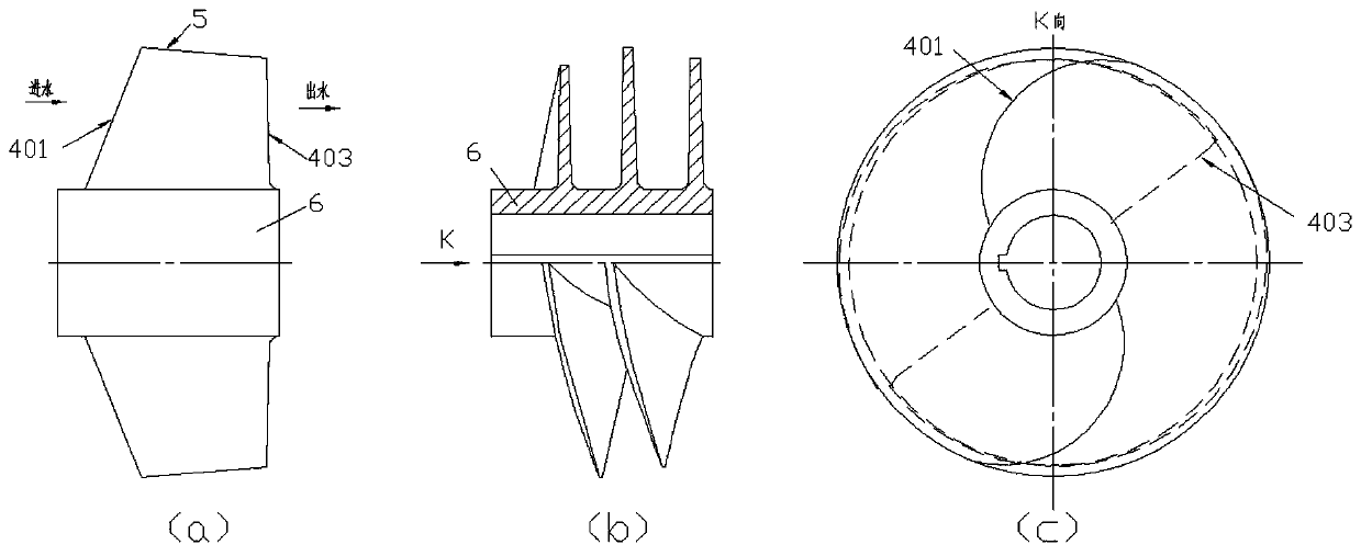
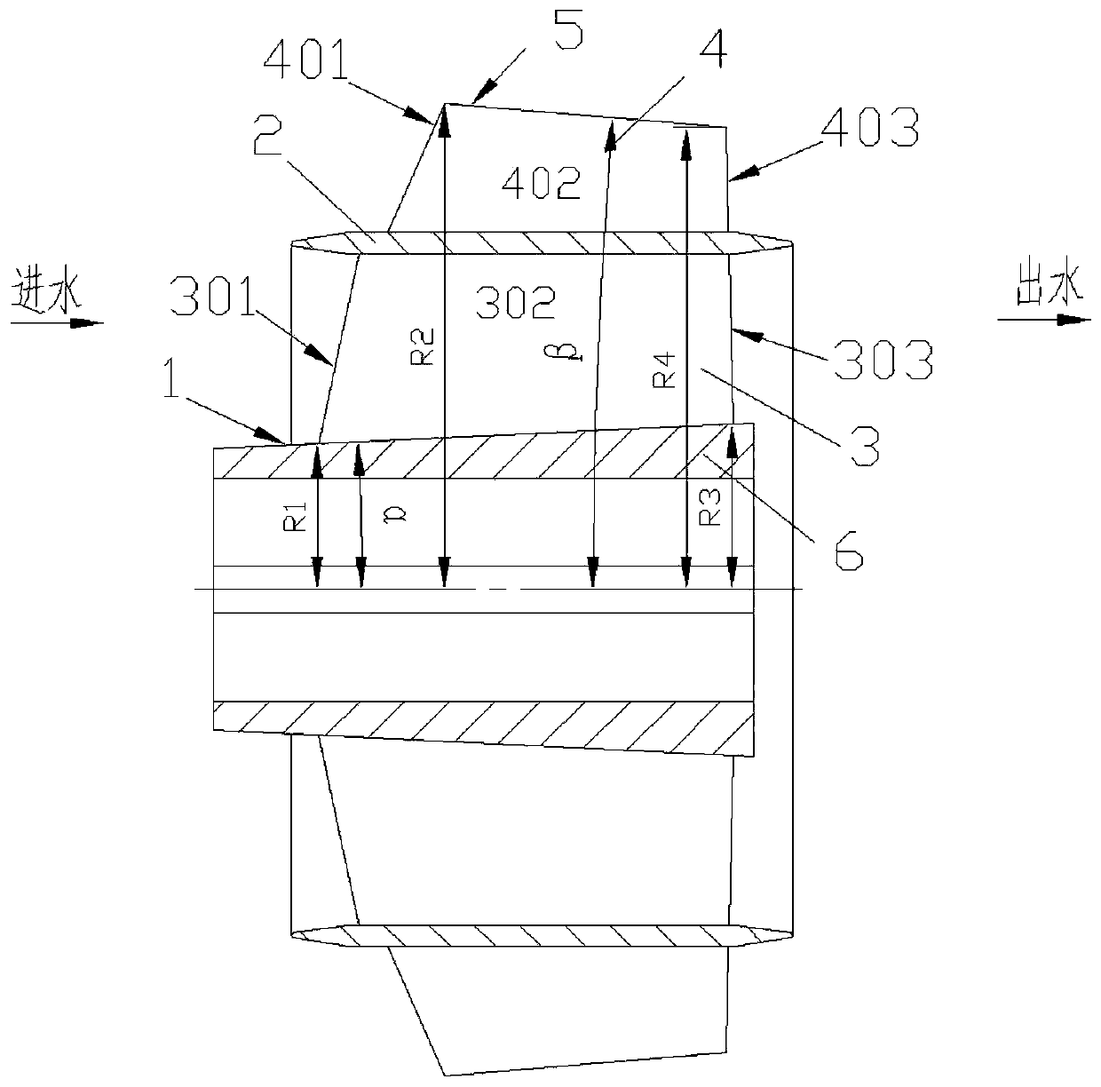
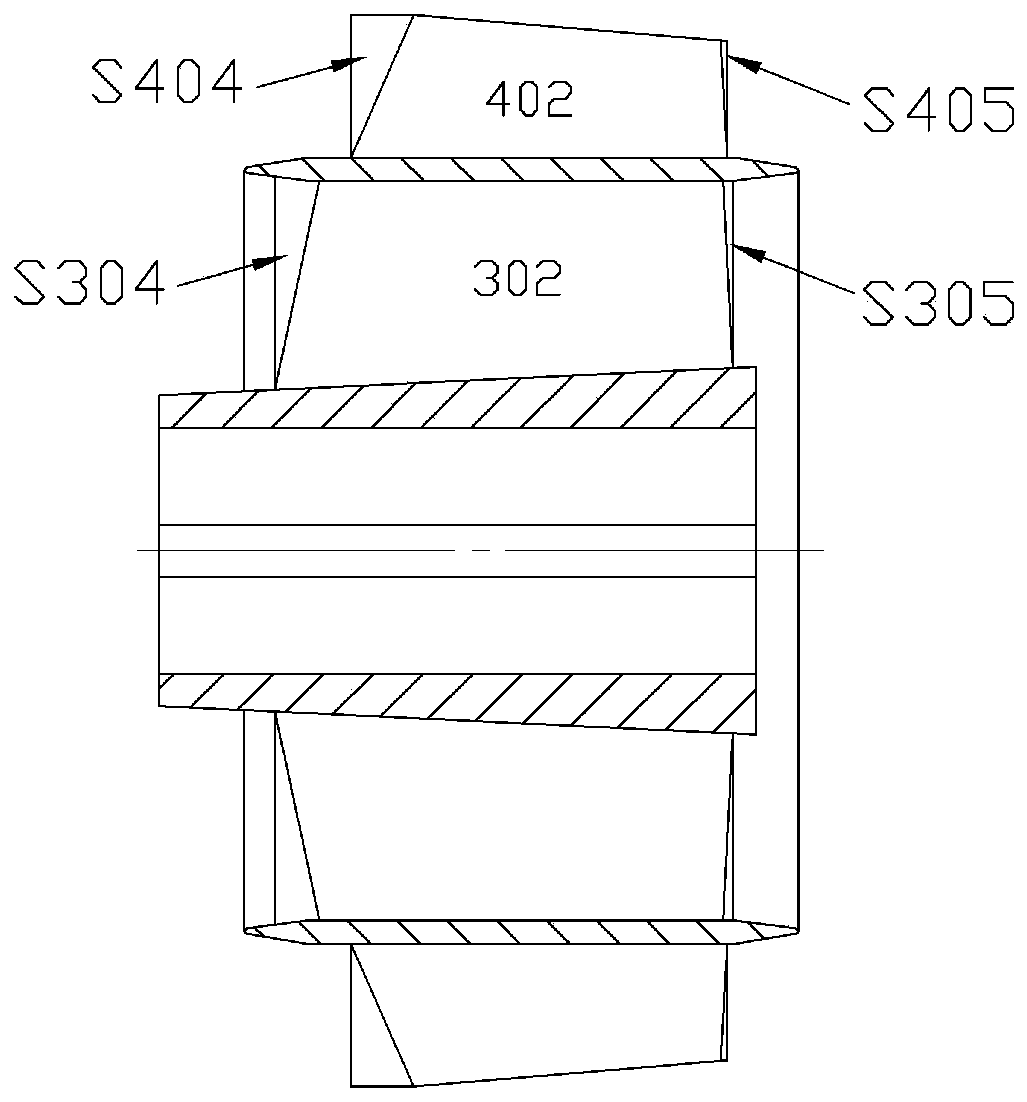
[0042] Embodiment 1 is the inducer of the 2-layer axial flow channel, such as figure 2 , image 3 and Figure 5As shown, in the inducer with high anti-cavitation performance of the present invention, the inducer hub 6 is the central area formed by the hub axial streamline 1 rotating 360° around the inducer axis center line, the inducer The outer side of the wheel hub 6 is provided with an axial surface flow channel A 3 and an axial surface flow channel B 4 which are not connected to each other, and the axial surface flow channel A 3 and the axial surface flow channel B 4 are separated by a flow channel dividing plate A 2 . The axial surface flow channel A3 is the inner axial surface flow channel, the axial surface flow channel B4 is the outer axial surface flow channel, the outer axial surface flow channel is located outside the inducer, and the inner axial surface flow channel is located on the outer axial surface Between the runner and the hub. The included angle α betwe...

Embodiment 2

[0055] Embodiment 2 is the inducer of 3 layers of mutually disconnected axial flow passages, such as Figure 6 As shown, the outer side of the hub 6 of the inducer is provided with an axial surface flow channel A 3, an axial surface flow channel B 4 and an axial surface flow channel C 8, and the axial surface flow channel A 3 and the axial surface flow channel C 8 pass through The channel dividing plate B 9 is isolated, and the axial channel B 4 and the axial channel C 8 are isolated by the channel dividing plate A 2 . The axial surface flow channel A 3 and the axial surface flow channel C 8 are both inner axial surface flow channels, the axial surface flow channel B 4 is the outer axial surface flow channel, the outer axial surface flow channel is located outside the inducer, and the inner shaft surface The surface flow channel is located between the outer axial surface flow channel and the hub. The blade 3 is arranged between the streamline side 1 of the axial surface of th...

Embodiment 3

[0056] Example 3 as Figure 7 As shown, on the basis of Example 1, the outer rim cover plate 7 is added to the outer flow line 5 of the axial flow channel B 4 to prevent leakage of the tip of the blade and further improve the anti-cavitation performance.

[0057] In the actual operation process, the inducer pressurizes the propellant to generate a certain head to increase the inlet pressure, avoid cavitation, and improve cavitation performance. However, during the high-speed operation of the inducer, its operating conditions often change, especially when the internal partial pressure drops below the saturated vapor pressure and cavitation occurs, which will lead to strong cavitation inside the inducer, causing performance Decline, the vibration of the system structure is strengthened, thus affecting the reliability of the entire device system and the service life of the inducer.

[0058] Taking the cavitation process on the blade A 302 as an example, under the condition of la...


PUM


Abstract

The invention provides an inducer with high cavitation resistance. The inducer is characterized in that at least two layers of meridional flow channels which do not communicate with each other are arranged on the outer side of a wheel hub of the inducer, and any two adjacent meridional flow channels are isolated by a flow channel partition plate; the cross section circulation area of any meridional flow channel is gradually reduced in the flow direction; the outlet area of any meridional flow channel is smaller than or equal to the inlet area; at least one blade is arranged in any meridional flow channel, and the blade inlet edges and the blade outlet edges in the different meridional flow channels are arranged in a staggered manner, so that the outflow uniformity of the inducer is improved; the blade inlet edges are swept back and rounded, so that the cavitation resistance is improved; and the blades are spiral blades, and the screw pitch of the spiral blades are equal screw pitch orvariable screw pitch or the combination of the equal screw pitch and the variable screw pitch. According to the inducer, the cavitation resistance is improved by increasing the number of the meridional flow channels.

Description

technical field [0001] The invention relates to the field of fluid machinery, in particular to an inducer with high anti-cavitation performance. Background technique [0002] Inducers are mostly used in aviation, aerospace, refrigeration and other occasions that require high cavitation. In the field of aviation and aerospace, because aerospace vehicles need to work at high altitudes or in space away from the ground, the structural size and quality of the propellant supply system are strictly limited by the constraints of the space size and structural quality of the vehicle. Propellant pumps require higher rotational speeds to minimize structural size and mass, while propellant tanks require lower pressures to reduce mass and size of tank pressurization systems. According to the characteristics of high rotational speed and low inlet pressure of the propellant pump in the propellant supply system, the propellant pump is required to have very high anti-cavitation performance. ...

Claims


Application Information

Patent Timeline
Patent Type & Authority Applications(China)
IPC IPC(8): F04D29/22F04D29/66
CPCF04D29/225F04D29/669
Inventor 付强朱荣生王秀礼龙云陈一鸣
Owner JIANGSU UNIV
Why Eureka
Try Eureka