Controllable microchannel heat pipe heat transfer device
A micro-channel heat pipe and heat pipe technology, applied in indirect heat exchangers, lighting and heating equipment, etc., can solve the problems of high heat transfer thermal resistance, large space occupation, low heat transfer efficiency, etc., and achieve broad market prospects and efficient utilization. Space, application environment friendly effect
- Summary
- Abstract
- Description
- Claims
- Application Information
AI Technical Summary
Problems solved by technology
Method used
Image
Examples
Embodiment 1
[0029] A controllable microchannel heat pipe heat transfer device involved in this embodiment is realized through the following technical scheme:
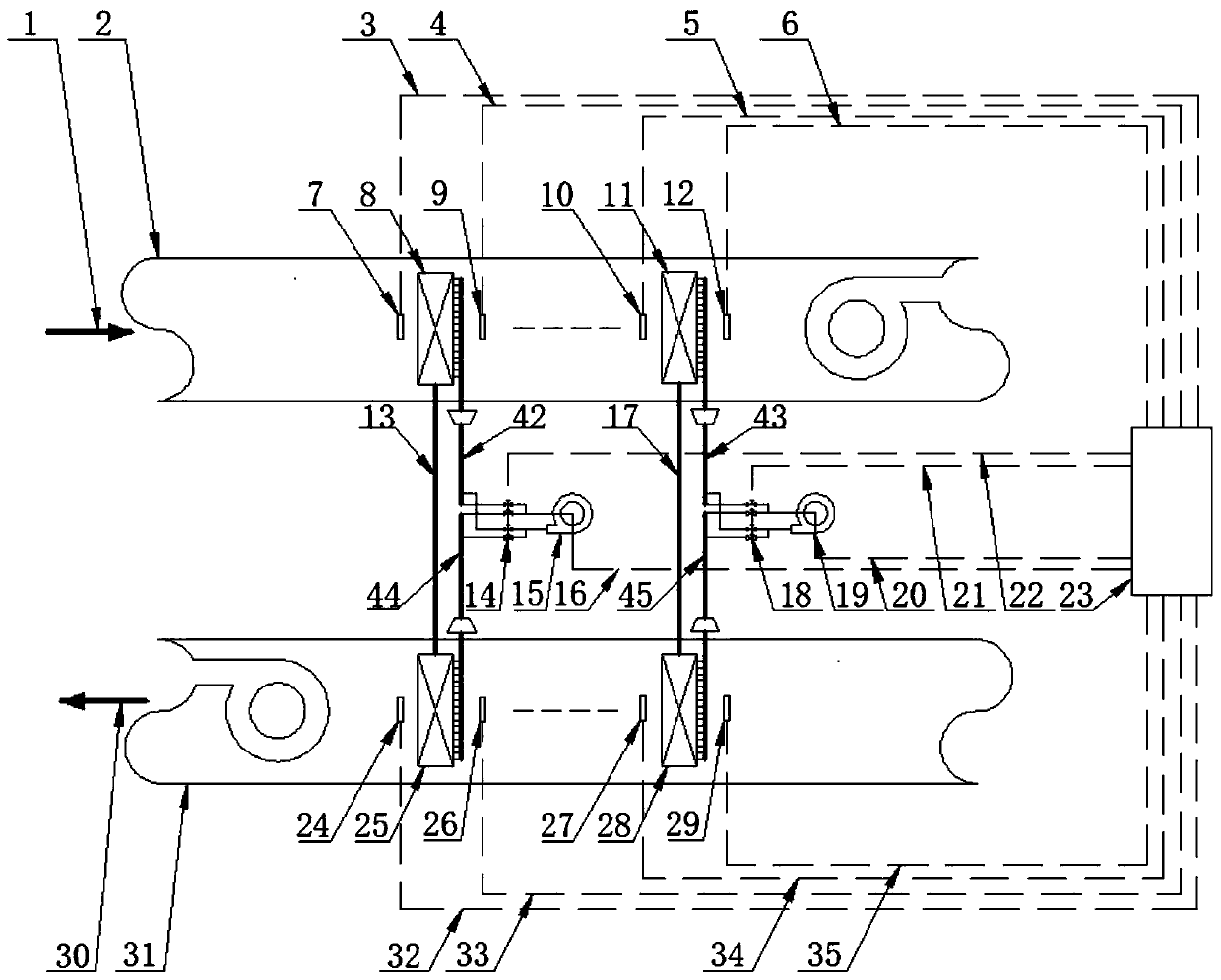
[0030] A air duct 2 and B air duct 31 are arranged in parallel, but the airflow direction is opposite, that is, the left side of A air duct 2 is the air intake end of airflow A1, and the left end of B air duct 31 is the exhaust end of airflow B30; In the passage, there are first-stage microchannel heat pipe heat exchanger 8 in air passage A and i-stage microchannel heat pipe heat exchanger 11 in air passage A, wherein i is an integer greater than or equal to 1. The left and right sides of the heat pipe heat exchanger 8 are provided with the front temperature sensor 7 of the first stage microchannel heat pipe heat exchanger of the A air duct and the rear sensor 9 of the first stage microchannel heat pipe heat exchanger of the A air duct for detection. The left and right sides of the i-th stage microchannel heat pipe heat exchanger 1...
Embodiment 2
[0037] like figure 1 As shown, this embodiment illustrates the structure and working process of the first embodiment, its main components are airflow A1, air duct A first-stage microchannel heat pipe heat exchanger front temperature sensor 7, air duct A first-stage microchannel heat pipe Heat exchanger 8, rear sensor of the first-stage microchannel heat pipe heat exchanger in air duct A 9, front temperature sensor 10 of the i-level micro-channel heat pipe heat exchanger in air duct A, and i-level microchannel heat pipe heat exchanger in air duct A 11. Temperature sensor behind the i-stage microchannel heat pipe heat exchanger of air duct A 12, first-stage heat pipe system reversing valve group 14, first-stage heat pipe system working fluid circulation pump 15, i-stage heat pipe system reversing valve group 18. Working fluid circulation pump of the i-th heat pipe system 19. PLC control cabinet 23. Temperature sensor in front of the first-stage microchannel heat pipe heat exchan...
Embodiment 3
[0041] like Figure 4 As shown, it is the structure and working process of the second embodiment of the present invention. Its main components are completely the same as in Embodiment 1 except for the reversing valve group. In Embodiment 1, the heat removal direction of the heat pipe is controlled by the reversing valve group. Control, embodiment 2 uses a four-way reversing valve instead of a reversing valve group to control the flow direction of the liquid-phase refrigerant, thereby controlling the direction of heat transfer.
[0042] The starting and running process of the system device is exactly the same as that of Embodiment 1.
[0043] The control process of the system device is exactly the same as that of Embodiment 1.
PUM
 Abstract
Description
Claims
Application Information
 - R&D
- Intellectual Property
- Life Sciences
- Materials
- Tech Scout
- Unparalleled Data Quality
- Higher Quality Content
- 60% Fewer Hallucinations
Browse by: Latest US Patents, China's latest patents, Technical Efficacy Thesaurus, Application Domain, Technology Topic, Popular Technical Reports.
© 2025 PatSnap. All rights reserved.Legal|Privacy policy|Modern Slavery Act Transparency Statement|Sitemap|About US| Contact US: help@patsnap.com


