
Plate sampling machine

A sampling machine and plate technology, which is applied in sampling, sampling devices, analyzing materials, etc., can solve the problems of high labor intensity of manual sampling, affecting the accuracy of detection, poor sample integrity, etc., so as to reduce labor intensity of workers and improve sampling efficiency. , the effect of good positioning

Inactive Publication Date: 2020-05-22
HOHHOT SIFANG ENG QUALITY TESTING CENT
View PDF0 Cites 4 Cited by
  • Summary
  • Abstract
  • Description
  • Claims
  • Application Information

AI Technical Summary

Problems solved by technology

In order to check whether the plate is qualified, it is necessary to test the strength, hardness, fire resistance and other properties of the plate. Before the test, it is necessary to select multiple samples of the same specification on the plate to facilitate the accuracy of the experiment; however, there is no special one at present. The sampling machine for sheet metal can only obtain samples by manually holding the sampling tube and turning the sampling tube manually. There are many problems in manual sampling. On the one hand, manual sampling is labor-intensive and low in efficiency; on the other hand, manual sampling During the process, there will be different deviations in the center and angle of the sampling tube, resulting in poor integrity of the sample obtained, which will affect the accuracy of the test due to unqualified samples.

Method used


Image

  • Plate sampling machine
  • Plate sampling machine
  • Plate sampling machine

Examples


Embodiment 1

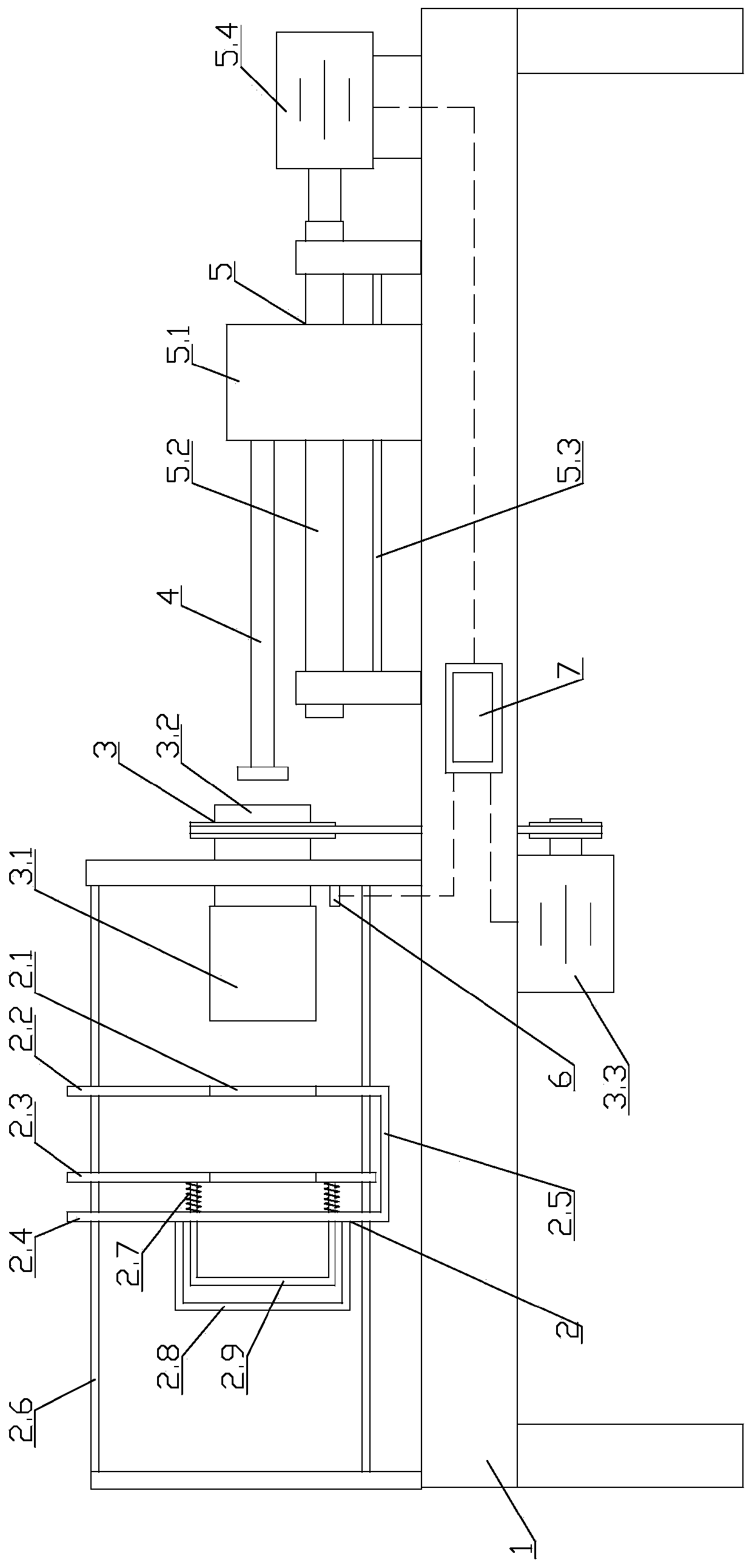
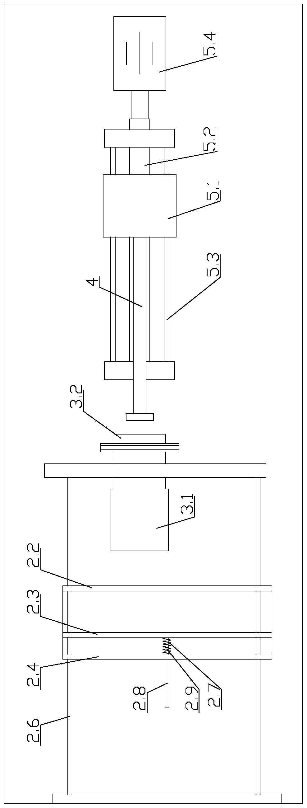
[0022] Embodiment 1: as figure 1 and figure 2 As shown, a plate sampling machine includes a main frame 1, a clamping mechanism 2, a sampling mechanism 3 and a push rod 4. On the top of the main frame 1, a clamping mechanism 2, a sampling mechanism 3 and a putter 4,

[0023] The clamping mechanism 2 is slidably arranged on the top of the main frame 1, and the sampling tube 3.1 of the sampling mechanism 3 is slidably arranged inside the sampling hole 2.1 of the clamping mechanism 2,

[0024] The sampling mechanism 3 includes at least one casing 3.2 that rotates vertically on the top of the main frame 1. Multiple casings 3.2 and matching sampling tubes 3.1 can be arranged side by side. The sampling tubes 3.1 and push rods 4 are in one-to-one correspondence with the sampling holes 2.1. , can realize intercepting multiple samples at the same time; the casing 3.2 is arranged along the sliding direction of the clamping mechanism 2, and the sampling motor 3.3 connected with the cas...

Embodiment 2

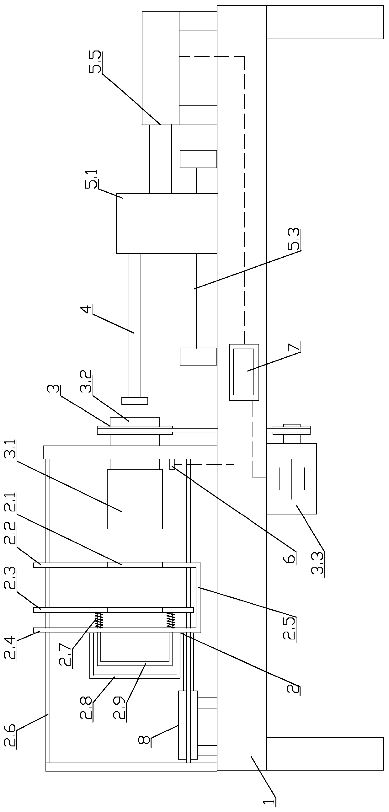
[0029] Embodiment 2: as image 3 As shown, its overall structure is the same as that of Embodiment 1, the difference is that the first push-pull structure 5 includes a telescopic rod 5.5, and the telescopic rod 5.5 is any one of a hydraulic cylinder, an air cylinder or an electric push rod. In this embodiment, the telescopic The rod 5.5 is preferably a cylinder, one end of the telescopic rod 5.5 is fixed with the main frame 1, and the other end of the telescopic rod 5.5 is fixed with a push rod 4, and the telescopic control push rod 4 of the telescopic rod 5.5 stretches into or withdraws from the sampling pipe 3.1; the controller 7 The output end of the telescopic rod is electrically connected to the telescopic rod 5.5, and the expansion and contraction of the telescopic rod 5.5 is controlled by the controller 7;

[0030] A second push-pull structure 8 connected to the clamping mechanism 2 is fixed on the top of the main frame 1. The second push-pull structure 8 controls the c...

Embodiment 3

[0031] Embodiment 3: as Figure 4 and Figure 5 As shown, its overall structure is the same as that of Embodiment 2, except that it also includes a stepping structure 9, and the stepping structure 9 includes a stepping motor 9.1, a driving sprocket 9.2, a driven sprocket 9.3, a chain 9.4 and a push plate 9.5; at the bottom of the connecting frame 2.5 between the first splint 2.2 and the second splint 2.3, a driving sprocket 9.2 and a driven sprocket 9.3 are rotated side by side, and the stepping motor 9.1 is connected to the driving sprocket 9.2. The outside of sprocket 9.2 and driven sprocket 9.3 is provided with chain 9.4, and the transmission direction of chain 9.4 is vertically set relative to second track 2.6, and driving sprocket 9.2, driven sprocket 9.3 and chain 9.4 constitute sprocket chain mechanism, Drive driving sprocket 9.2 to rotate by stepping motor 9.1, and then drive chain 9.4 to rotate; The controller 7 controls the opening and closing of the stepping motor...


PUM


Abstract

The invention discloses a plate sampling machine which comprises a main rack, a clamping mechanism, a sampling mechanism and a push rod. The clamping mechanism, the sampling mechanism and the push rodare sequentially arranged at the top of the main rack from one end to the other end, the clamping mechanism is slidably arranged at the top of the main rack, the sampling pipe of the sampling mechanism is slidably arranged in the sampling hole of the clamping mechanism, and the push rod is movably arranged in the sampling pipe; a first push-pull structure connected with the push rod is fixed at the top of the main rack and controls the push rod to move along the axial direction of the sampling pipe. The plate sampling machine has the advantages that automatic sampling is achieved through cooperation of the clamping mechanism and the sampling mechanism, manual sampling is replaced, the labor intensity of workers can be effectively reduced and sampling efficiency is improved; the clamping mechanism can play a good role in positioning the plate, and the sampling pipe is driven by the sampling motor so that the consistency of the sampling center and angle can be ensured, the integrity ofthe obtained sample is ensured and the precision and the accuracy of detection are further improved.

Description

Technical field: [0001] The invention relates to the technical field of plate sampling, in particular to a plate sampling machine. Background technique: [0002] Sheet material is a flat rectangular building material board of standard size, used in the construction industry, and used as a component of walls, ceilings or floors. It also refers to forged, rolled or cast metal plates. In order to check whether the plate is qualified, it is necessary to test the strength, hardness, fire resistance and other properties of the plate. Before testing, it is necessary to select multiple samples of the same specification on the plate to facilitate the accuracy of the experiment; For plate sampling machines, samples can only be obtained by manually holding the sampling tube and rotating the sampling tube manually. There are many problems in manual sampling. On the one hand, manual sampling is labor-intensive and low in efficiency; on the other hand, manual sampling During the process...

Claims


Application Information

Patent Timeline
Patent Type & Authority Applications(China)
IPC IPC(8): G01N1/08
CPCG01N1/08G01N2001/085
Inventor 魏军魏聚琦
Owner HOHHOT SIFANG ENG QUALITY TESTING CENT
Learn More