Strings for changing the direction of fluid flow

A pipe string and fluid technology, applied in the field of pipe strings that change the flow direction of the fluid, can solve the problems of large leakage, easy to occur complex situations, adverse effects, etc., and achieve the effect of solving lost circulation

Active Publication Date: 2021-04-13
CHINA PETROLEUM & CHEM CORP +1
View PDF11 Cites 0 Cited by
  • Summary
  • Abstract
  • Description
  • Claims
  • Application Information

AI Technical Summary

Problems solved by technology

This will cause problems such as long processing cycle and large leakage.
In addition, for deep wells, ultra-deep wells, etc., complex situations are prone to occur during the tripping process, which is likely to bring other adverse effects

Method used


Image

  • Strings for changing the direction of fluid flow
  • Strings for changing the direction of fluid flow
  • Strings for changing the direction of fluid flow

Examples


Embodiment Construction

[0027] The present invention will be further described below in conjunction with accompanying drawing.

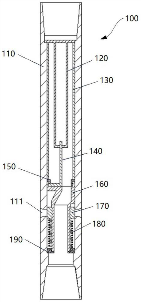
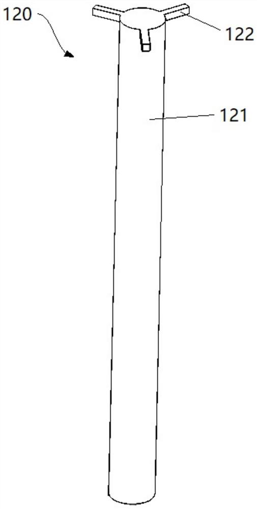
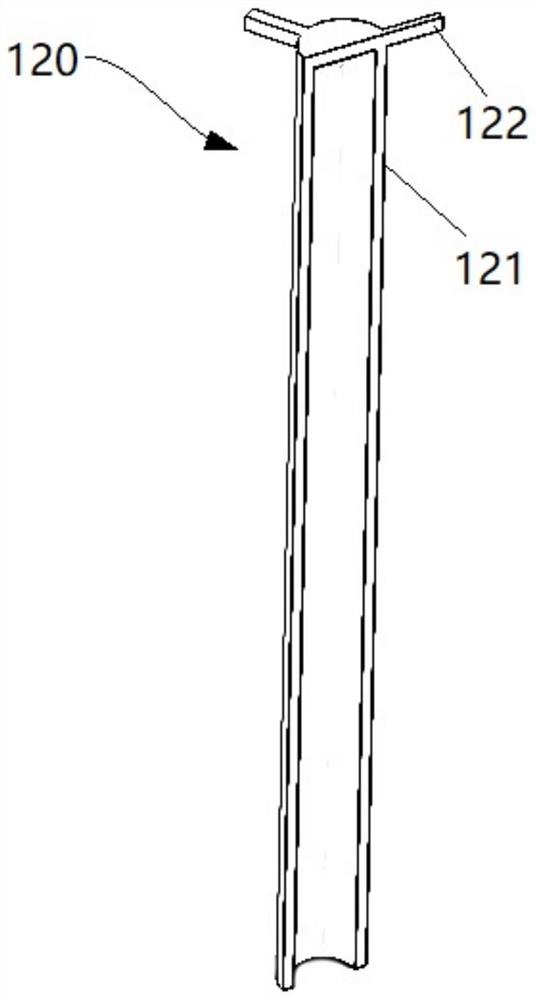
[0028] figure 1 A cross-sectional view of a tubing string 100 according to an embodiment of the invention is schematically shown. Such as figure 1 As shown, the tubing string 100 includes a generally cylindrical outer barrel 110 capable of communicating with upstream and downstream tubing strings such that the tubing string 100 forms part of an overall drilling tool.

[0029] A reversing cylinder 160 is sheathed in the pipe string 100 , and the reversing cylinder 160 forms two channels separated from each other, namely, a first flow channel and a second flow channel. The first flow passage communicates from the upper end of the reversing cylinder 160 to the lower end of the reversing cylinder 160, leading to the downstream pipe string. The second flow channel leads from the upper end of the reversing cylinder 160 to the annular space outside the pipe string 100 (ie, outs...


PUM


Abstract

The invention relates to a pipe string for changing the flow direction of fluid, the pipe string comprises: a reversing cylinder, the reversing cylinder comprises a pipe leading from the upper end of the reversing cylinder to the reversing cylinder A first flow passage at the lower end of the reversing cylinder, and a second flow passage leading from the upper end of the reversing cylinder to the annulus outside the pipe string, the first flow passage and the second flow passage are separated ; and a first switch mechanism configured to selectively close the first flow passage or the second flow passage. The fluid can be introduced into the annulus according to the needs through this pipe string, so that the problems of lost circulation and the like can be effectively and conveniently solved.

Description

technical field [0001] The invention relates to the technical fields of oil, natural gas, shale gas and coalbed methane drilling, in particular to a pipe string for changing the direction of fluid flow. Background technique [0002] During the drilling process of oil, natural gas, shale gas and coalbed methane, complex situations such as lost circulation, well overflow and clogged water holes are often encountered. For example, when lost circulation occurs, it is necessary to trip out the drill to replace the drilling tool assembly and carry out the plugging operation. This will cause problems such as long processing cycle and large leakage. In addition, for deep wells, ultra-deep wells, etc., complex situations are likely to occur during the tripping process, which is likely to bring other adverse effects. [0003] Therefore, need a kind of device that can solve problems such as well leakage easily. Contents of the invention [0004] In view of the above problems, the ...

Claims


Application Information

Patent Timeline
Patent Type & Authority Patents(China)
IPC IPC(8): E21B17/18
CPCE21B17/18
Inventor 刘鹏丁士东王立双马广军杨枝王玉娟江山红邓大伟亢武臣
Owner CHINA PETROLEUM & CHEM CORP
Why Eureka
Try Eureka